
E03. 3.3 V Logic, Power Rails and Level Shifting
Learn the 3.3 V rule that keeps ESP32 pins safe, then wire a button and an LED the safe way.
Learning outcomes
- State why 5 V must never go into an ESP32 pin
- Identify the USB, VIN and 3V3 power pins on a DevKit
- Use a two-resistor divider to bring a 5 V signal down to about 3 V
- Read a button with INPUT_PULLUP and light an LED while it is held
Parts and preparation
ESP32 DevKit, USB data cable, push-button, LED + 220-330 ohm resistor, jumper wires. Optional: two resistors (e.g. 2.2 k ohm and 3.3 k ohm) for the voltage divider demo.
Before power: inspect wiring, confirm supply voltage and ensure all connected circuits share GND.
What you will do
Learn the one rule that protects every ESP32: no 5 V into the pins. Then wire a button and an LED the safe way.
Sketch 1 reads the button and prints pressed or open. Sketch 2 lights the LED while you hold the button down.

Never put 5 V into an ESP32 pin
Uno pins use 5 V. ESP32 pins use 3.3 V. A 5 V signal - from an Uno pin or from many sensor modules - can damage an ESP32 pin for good. If a part sends out 5 V, bring it down to 3.3 V first, or buy the 3.3 V version of the part.
The power pins
USB powers the board while you are learning. The 3V3 pin gives out 3.3 V for small parts such as sensors and potentiometers. Never connect 5 V to the 3V3 pin, and never power motors or long LED strips from it. Always connect the GND of every part to the ESP32 GND.
| Pin | Use it for |
|---|---|
| USB | Powering the board from the PC |
| VIN / 5V | Bringing in 5 V from another supply (if your board allows it) |
| 3V3 | Powering small 3.3 V parts |
| GND | The shared return - connect every part's GND here |
Bringing 5 V down with two resistors
Two resistors in a row make a voltage divider. The point between them sits at a lower voltage, which is safe for the ESP32.
Course example: 2.2 k ohm from the 5 V signal, 3.3 k ohm to GND. The middle point is about 3 V. The HC-SR04 distance sensor's Echo pin is a common 5 V signal that needs this.

// Vout = Vin x R2 / (R1 + R2)
// 5 V x 3.3k / (2.2k + 3.3k) = 3.0 V  - safe for the ESP32
Level shifter modules
A divider only works one way (5 V in, 3 V out). For wires that carry signals both ways, such as I2C, buy a small level shifter module instead.
Why the button is on GPIO 4
GPIO 0 is checked by the ESP32 at start-up. A button there can stop the board starting normally. GPIO 4 is a safe choice, so the course uses it for buttons.
Wiring and safe build sequence
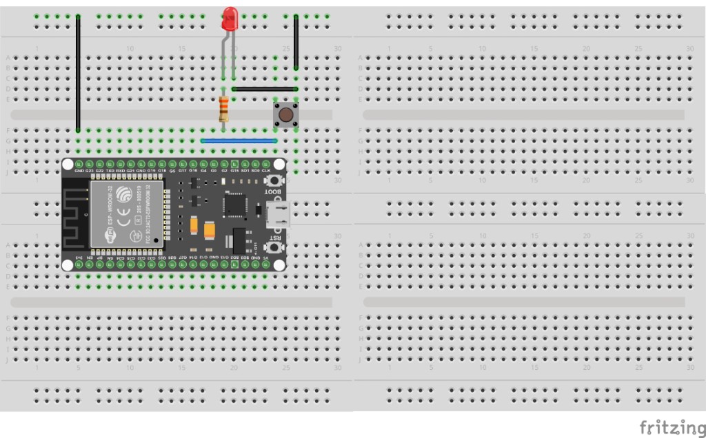
- ESP32 GPIO 4 -> one side of the push-button; other side -> GND
- Sketch 2: GPIO 2 -> 220-330 ohm -> LED long leg; LED short leg -> GND (or use the on-board LED)
- USB power; Serial Monitor 115200
Worked sketch 1: Read the button
Download .inoWhat this sketch is for: Press and release the button and watch the Serial Monitor.
const int buttonPin = 4;                // the button is between GPIO 4 and GND

void setup() {                           // runs once
  pinMode(buttonPin, INPUT_PULLUP);      // the pin reads HIGH until the button is pressed
  Serial.begin(115200);                  // start Serial at the ESP32 speed
}

void loop() {                            // runs over and over
  if (digitalRead(buttonPin) == LOW) {   // LOW means the button is pressed
    Serial.println("pressed");           // say so
  } else {                               // otherwise the pin reads HIGH
    Serial.println("open");              // the button is not pressed
  }
  delay(200);                            // slow the printing down
}
How the code works
- INPUT_PULLUP: the pin reads HIGH when the button is open and LOW when it is pressed.
- The button connects to GND, never to 5 V - so the pin only ever sees 3.3 V or 0 V.
Worked sketch 2: Hold the button to light the LED
Download .inoWhat this sketch is for: Add the LED, then hold the button down. Match the breadboard layout below before upload.
const int buttonPin = 4;                // the button is between GPIO 4 and GND
const int ledPin = 2;                   // the LED (with its resistor) is on GPIO 2

void setup() {                          // runs once
  pinMode(buttonPin, INPUT_PULLUP);     // the pin reads HIGH until the button is pressed
  pinMode(ledPin, OUTPUT);              // the LED pin is an output
}

void loop() {                           // runs over and over
  if (digitalRead(buttonPin) == LOW) {  // is the button pressed?
    digitalWrite(ledPin, HIGH);         // yes - LED on
  } else {                              // no
    digitalWrite(ledPin, LOW);          // LED off
  }
}
How the code works
- The LED follows the button: on while held, off when released.
- Keep the series resistor on an external LED - it limits the current.
- Build from the breadboard photo: button on GPIO 4, LED on GPIO 2.
Test and record evidence
Practical evidence checklist
Common faults and checks
- Always open: check the button legs and the GND wire.
- Always pressed: the button may be turned 90 degrees on the breadboard - try rotating it.
- LED never lights: check the LED's long leg goes towards GPIO 2, and the resistor is in place.
- Board will not start with the button wired: make sure it is on GPIO 4, not GPIO 0.
Check your understanding
Q1. What voltage do ESP32 pins use?
Show answer
3.3 V - never apply 5 V.
Q2. What must every part share with the ESP32?
Show answer
GND.
Q3. What does a voltage divider do?
Show answer
It turns a higher voltage (such as 5 V) into a lower one (about 3 V) using two resistors.
Q4. With INPUT_PULLUP, what does a pressed button read?
Show answer
LOW.
Q5. Why is the button on GPIO 4 and not GPIO 0?
Show answer
GPIO 0 is checked at start-up, and a button there can stop the board starting normally.
Q6. Why should you not power a long LED strip from the 3V3 pin?
Show answer
It can only supply a small current - use a separate 5 V supply.
Q7. When do you need a level shifter module instead of a divider?
Show answer
When the wire carries signals both ways, such as I2C.