
E17. Capstone: Networked Room Node
Put it together: a web page shows a live room level from a pot, an alert LED lights above a threshold, and /json serves the same data to programs.
Learning outcomes
- Combine Wi-Fi, analogRead and a web server in one sketch
- Explain the three jobs loop() does: read, decide, answer
- Show a live reading on a web page that refreshes itself
- Light an alert LED when the reading passes a threshold
- Serve the same data as JSON at /json
- Build and test one block at a time, and say whether a fault is wiring, Wi-Fi or code
Parts and preparation
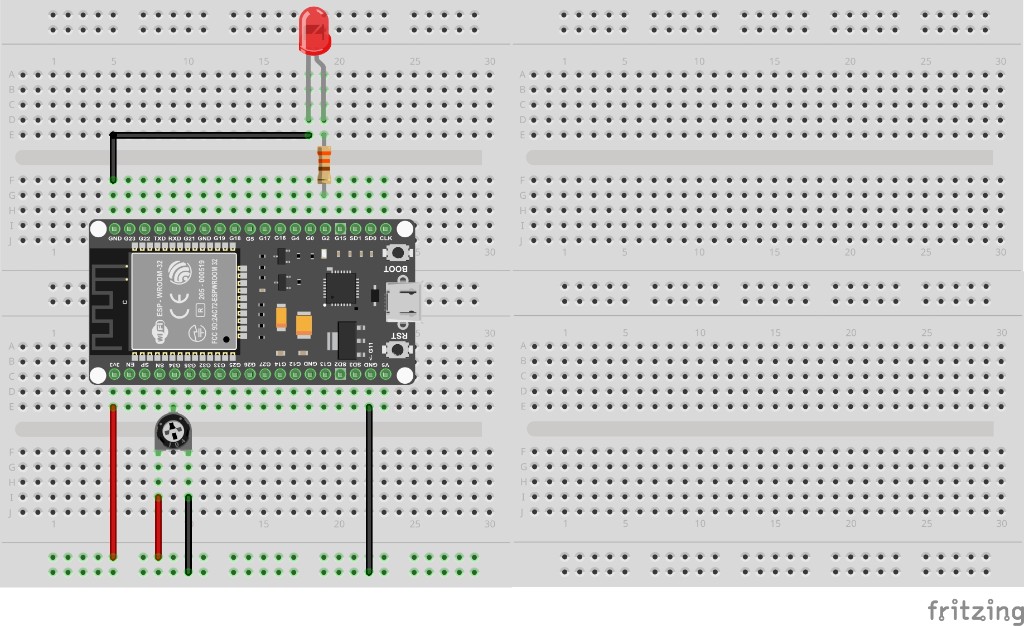
ESP32 DevKit, USB data cable, 10 k ohm potentiometer on GPIO 34 (stand-in for a room sensor), LED + series resistor on GPIO 2 (alert lamp), breadboard and jumpers, a phone or PC on the same Wi-Fi. Library: ArduinoJson by Benoit Blanchon (from ESP32 Lesson 10).
Before power: inspect wiring, confirm supply voltage and ensure all connected circuits share GND.
Libraries for this lesson
In Arduino IDE 2 open Tools → Manage Libraries…. Search by the Library Manager name and install the package by the exact author below. Similar names from other authors can use different APIs and will break the example.
| Include | Library Manager name | Author | Install note |
|---|---|---|---|
WiFi.h | WiFi | Espressif | Built into the esp32 Arduino core. |
WebServer.h | WebServer | Espressif | Built into the esp32 Arduino core. |
ArduinoJson.h | ArduinoJson | Benoit Blanchon | Already installed in ESP32 Lesson 10. |
What you will build
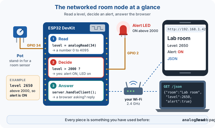
You are building a room monitor for your bench. A device like this is called a node: a small board that measures something and shares it over the network.
A knob (a potentiometer, or pot) stands in for a real room sensor, such as a light sensor. Turn it and the room level changes. When the level goes above a limit you choose - the threshold - a red alert LED lights. Anyone on the same Wi-Fi can open the node's web page on a phone and watch the level, and other programs can read the same numbers from /json.
Every piece is something you have done before: analogRead (ESP32 Lesson 04), a web page (ESP32 Lesson 09) and JSON (ESP32 Lesson 10). The new skill is making them work together in one sketch, and testing them one block at a time so you always know where a problem is.
The three jobs in loop()
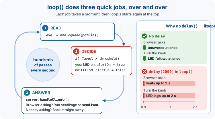
The whole sketch comes down to three jobs that loop() does again and again:
1. Read: level = analogRead(potPin) measures the knob as a number from 0 to 4095.
2. Decide: if the level is above the threshold, switch the alert LED on and remember alertOn = true; otherwise switch it off and remember false.
3. Answer: server.handleClient() checks whether a browser is asking for something. If one is, it runs sendPage() or sendJson(). If nobody is asking, it comes straight back.
One pass takes about a millisecond, so loop() runs hundreds of times every second. That is why there is no delay() in loop(): a delay(2000) would freeze all three jobs, so the LED would lag behind the knob and a browser could wait 2 seconds for an answer.
setup() does the one-time work first: it makes the LED pin an output, joins the Wi-Fi, prints the address and tells the web server which function answers which path.
Pins: why GPIO 34 and 3V3
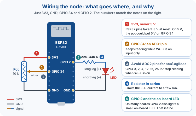
The ESP32 has two sets of analog input pins, called ADC1 and ADC2. The Wi-Fi radio borrows ADC2 while it is on, so analogRead on an ADC2 pin stops working as soon as the node joins your network. GPIO 34 is an ADC1 pin, so it keeps reading with Wi-Fi on. It is also input only - perfect for a sensor, but it cannot drive an LED and has no built-in pull-up.
Power the pot from 3V3, never 5V. The middle leg can reach whatever voltage the outer legs have, and an ESP32 pin must never see more than 3.3 V.
The alert LED is on GPIO 2 with a 220-330 ohm resistor in series, which keeps the current to a few milliamps. On many DevKits GPIO 2 also drives a small on-board LED, so you may see two lights together - that is fine.
| Part | Wiring | Why |
|---|---|---|
| Pot outer legs | 3V3 and GND | Pins must stay at or below 3.3 V |
| Pot middle leg | GPIO 34 | ADC1: still reads while Wi-Fi is on |
| Alert LED | GPIO 2 -> 220-330 ohm -> LED -> GND | The resistor limits the current |
From knob to number
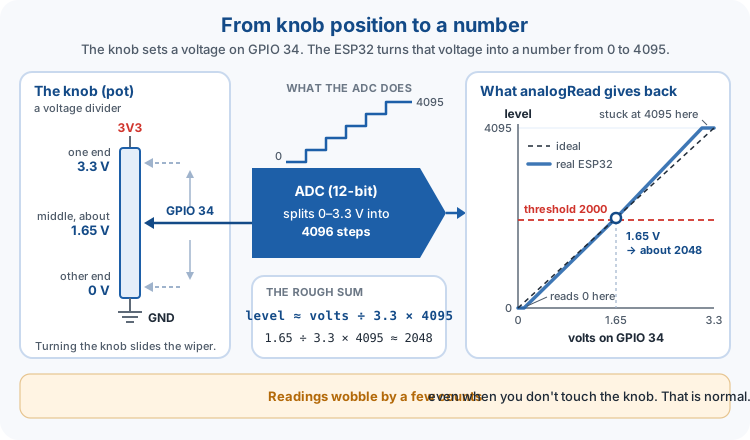
The pot is a voltage divider. Its middle leg gives 0 V at one end of the turn, 3.3 V at the other, and about 1.65 V in the middle.
The ESP32's ADC (analog-to-digital converter) measures that voltage and turns it into a whole number. It is 12-bit, which means 4096 steps: 0 for 0 V up to 4095 for the top of its range. As a rough guide, level = volts / 3.3 x 4095, so the middle of the knob reads about 2048.
The ESP32's ADC is not perfect. It reads 0 for the first tenth of a volt or so, and stops at 4095 a little before 3.3 V. The number also wobbles by a few counts even when you do not touch the knob. None of that matters here: you only need to know whether the level is above or below the threshold.
The threshold decides the alert
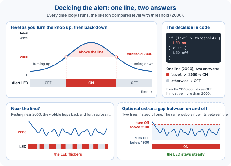
The threshold is the line between "all fine" and "alert". The sketch starts at 2000, roughly half way round the knob:
Level above 2000: alertOn becomes true and the LED comes on.
Level 2000 or below: alertOn becomes false and the LED goes off.
alertOn is a bool, a variable that is only ever true or false. The page and the JSON both read it, so they always agree with the LED.
With a real sensor you would choose the threshold from readings: watch the level on Serial in normal conditions and in alert conditions, then pick a number between them. If you hold the knob right on the line, the LED may flicker because the reading wobbles across it. That is normal for this simple version; a fix is one of the extras at the end.
if (level > threshold) {                  // above the threshold?
  alertOn = true;                         // remember the alert is on
  digitalWrite(alertPin, HIGH);           // alert LED on
} else {                                  // at or below the threshold
  alertOn = false;                        // remember the alert is off
  digitalWrite(alertPin, LOW);            // alert LED off
}
How your phone finds the ESP32
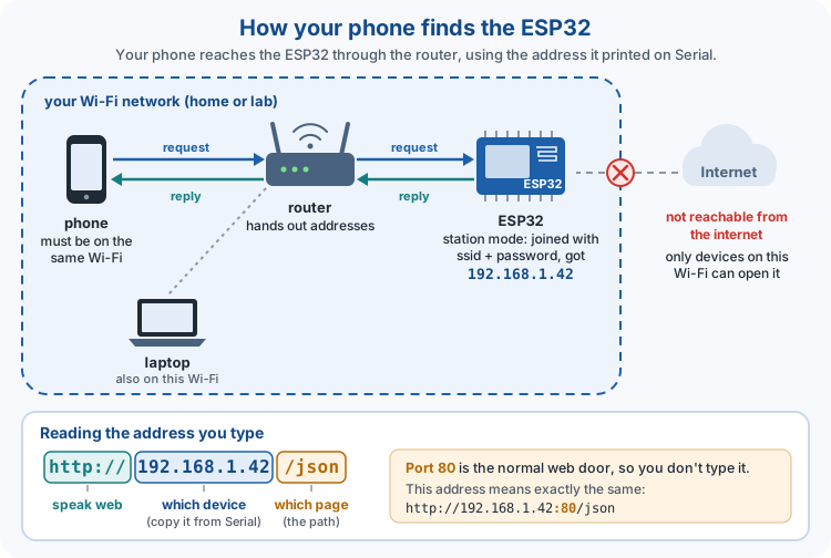
The node uses station mode: like your phone, it joins your existing Wi-Fi with the network name (ssid) and password. When it joins, the router gives it an address on that network, such as 192.168.1.42, and the sketch prints it on Serial.
To open the page, type that address into a browser on a phone or PC on the same Wi-Fi. A web address has three parts: http:// says "speak web", 192.168.1.42 says which device, and the path, such as / or /json, says which page. The web server listens on port 80, the normal web door, so you never need to type the port.
The address is local: it only works for devices on your Wi-Fi, not from mobile data or across the internet. That keeps a bench project private. It also means anyone on the same Wi-Fi can open the page, so never put passwords or private data on it.
One request, start to finish
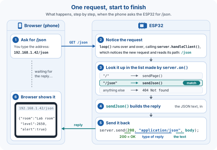
When you open http://192.168.1.42/json, this is what happens:
1. The browser sends a request: GET /json, which means "please send me the page at /json".
2. On its next pass of loop(), server.handleClient() notices the request.
3. The server looks up /json in the list you made with server.on() in setup(), and finds sendJson().
4. sendJson() builds the JSON text from the latest level and alertOn.
5. server.send(200, "application/json", body) sends it back. 200 means "OK", the middle part says what type of text it is, and body is the text itself.
6. The browser shows the JSON.
A path that is not in the list, such as /hello, gets the reply 404 Not found. That is a quick way to spot a typing mistake in an address.
| Path | Function | Reply |
|---|---|---|
| / | sendPage() | The web page for people (text/html) |
| /json | sendJson() | The data for programs (application/json) |
| anything else | (none) | 404 Not found |
A page that refreshes itself
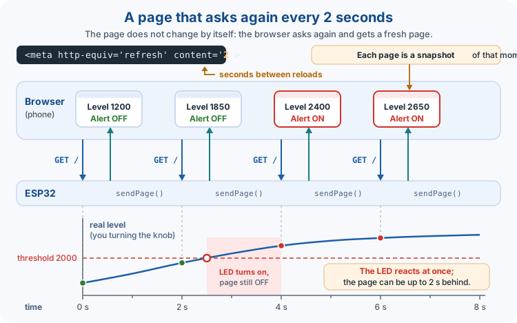
The page starts with <meta http-equiv='refresh' content='2'>. This line tells the browser to ask for the page again every 2 seconds, so the level stays live without you pressing refresh.
Each reply is a snapshot: sendPage() builds a brand-new page from the level at that moment. Between snapshots the page does not change, so it can be up to 2 seconds behind the knob - but the LED reacts at once, because loop() is checking all the time.
Why not refresh faster? Every reload is a new request for the ESP32 to answer. Every 2 seconds is plenty for a room level and keeps the node relaxed.
Building the page from text
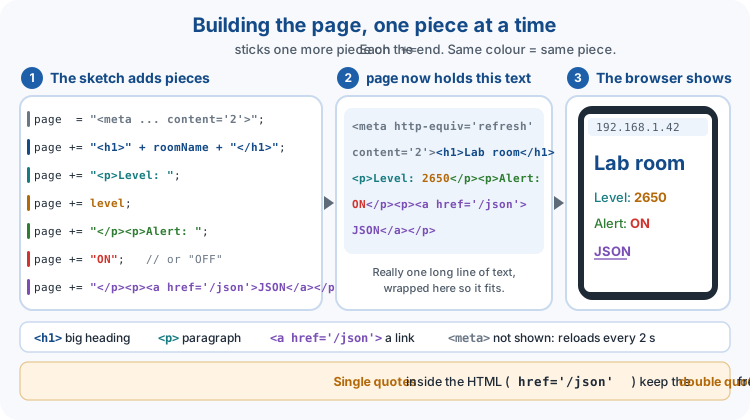
A web page is just text written in HTML. sendPage() builds it in a String called page, one piece at a time: page = starts it, and each page += adds more on the end.
Three HTML tags do all the work: <h1> makes a big heading, <p> makes a paragraph, and <a href='/json'> makes a link to /json. Each one is closed with a matching </h1>, </p> or </a>.
page += level adds the number as text, so 2650 becomes the characters 2650. Inside the HTML the sketch uses single quotes, so the double quotes stay free to mark where the Arduino text starts and ends.
Same numbers, two formats
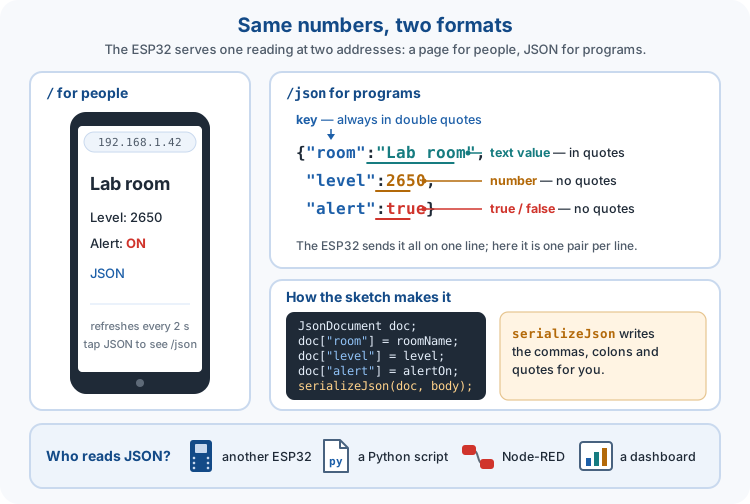
The node shares its data twice. The page at / is for people: headings and words a browser shows nicely. /json is for programs: plain data that is easy for code to pick apart.
{"room":"Lab room","level":2650,"alert":true}
JSON is made of key-value pairs. The key is the name, always in double quotes. The value can be text in quotes ("Lab room"), a number without quotes (2650), or true or false without quotes.
You do not type that text yourself. The sketch fills a JsonDocument - doc["level"] = level - and serializeJson() writes the quotes, colons and commas for you, so they are always right. Another ESP32 (ESP32 Lesson 10), a Python script or a dashboard such as Node-RED can then read your node.
Build it in five tested steps
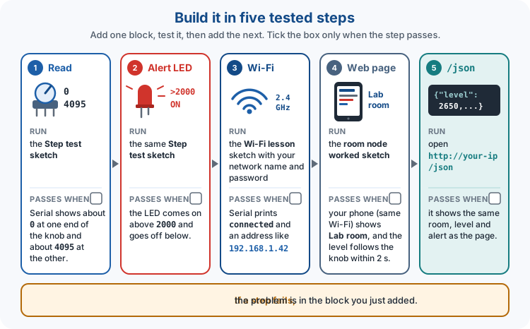
Do not type the whole sketch and hope. Add one block, upload, check it works, then add the next. If something breaks, the problem is in the block you just added.
1. Read: run the Step test sketch below. Pass: Serial shows about 0 at one end of the knob and about 4095 at the other.
2. Alert LED: same sketch. Pass: the LED comes on above 2000 and goes off below.
3. Wi-Fi: run the sketch from ESP32 Lesson 08 with your network name and password. Pass: Serial prints connected and an address.
4. Web page: run the room node worked sketch. Pass: your phone shows Lab room and the level follows the knob within 2 seconds.
5. /json: open http://your-address/json. Pass: it shows the same room, level and alert as the page.
Wiring, Wi-Fi or code?
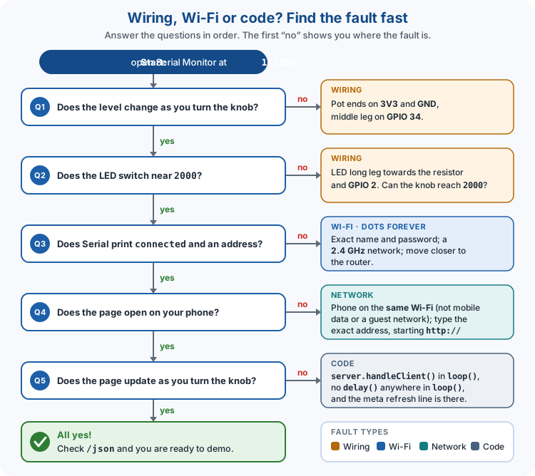
When something does not work, find which layer the fault is in before changing anything. Open Serial Monitor at 115200 and work down the questions in order - each yes rules out a whole layer.
The level does not change: wiring. The LED does not switch: wiring, or a threshold the knob cannot reach. Only dots on Serial: Wi-Fi. The page will not open: network - the phone or the address. The page opens but does not update: code.
Assessment checklist (pass level)
A reliable demo comes first. Extra features do not make up for a node that does not work.
Demo in this order: show the IP address on Serial, open the page on a phone, turn the knob past the threshold so the LED and the page both change, then open /json and point out the same numbers.
| Criterion | What good looks like |
|---|---|
| Starts up | IP address on Serial; correct board and port |
| Web page | Level changes as you turn the pot |
| Alert | LED clearly on above the threshold, off below |
| JSON | /json shows the same numbers as the page |
| Safety | Pot on 3V3; resistor in series with the LED |
| Explain | Station mode, handleClient and why GPIO 34, in your own words |
| Fault-find | Say whether a fault is wiring, Wi-Fi or code |
Extras, only after a pass
Not required. Pick at most one, and keep a copy of your working sketch first:
Real sensor: swap the pot for a light sensor (an LDR from GPIO 34 to 3V3, with a 10 k ohm resistor from GPIO 34 to GND). The sketch stays the same; set a new threshold from the readings.
No flicker: use two lines - turn the alert on above 2100 and off only below 1900.
Publish the level with MQTT (ESP32 Lesson 11), show it as NeoPixel colours (ESP32 Lesson 06 and ESP32 Lesson 07), or add OTA updates (ESP32 Lesson 16).
Wiring and safe build sequence
- Potentiometer: 3V3 -> one end, GND -> other end, middle leg -> GPIO 34
- Alert LED: GPIO 2 -> 220-330 ohm -> LED long leg; LED short leg -> GND
- USB for power; phone or PC on the same Wi-Fi as the ESP32
Step test sketch: read the pot and switch the LED
Download .inoWhat this sketch is for: Steps 1 and 2, with no Wi-Fi yet. Open Serial Monitor at 115200 and turn the knob: the level should run from about 0 to about 4095, and the LED should come on above 2000. Use the same breadboard as the worked sketch.
const int potPin = 34;                    // the pot (room sensor stand-in) is on GPIO 34
const int alertPin = 2;                   // the alert LED is on GPIO 2
const int threshold = 2000;               // above this level, the alert comes on

void setup() {                            // runs once
  Serial.begin(115200);                   // start Serial at the ESP32 speed
  pinMode(alertPin, OUTPUT);              // the alert LED pin is an output
  analogReadResolution(12);               // readings will be 0 to 4095
}

void loop() {                             // runs over and over
  int level = analogRead(potPin);         // read the room level, 0 to 4095

  Serial.print("Level: ");                // a label
  Serial.print(level);                    // the reading

  if (level > threshold) {                // above the threshold?
    digitalWrite(alertPin, HIGH);         // alert LED on
    Serial.println("  Alert: ON");        // finish the line with ON
  } else {                                // at or below the threshold
    digitalWrite(alertPin, LOW);          // alert LED off
    Serial.println("  Alert: OFF");       // finish the line with OFF
  }

  delay(200);                             // 5 lines a second is easy to read
}
How the code works
- This is the Read and Decide part of the room node, on its own.
- Write down the level at each end of the knob and in the middle. You will need them to explain your threshold.
- delay(200) is fine here because nothing else is running. The worked sketch has no delay, so it can answer browsers.
- Level stuck at 0 or 4095? Check the pot's middle leg is on GPIO 34 and its ends are on 3V3 and GND.
Worked sketch: Room node
Download .inoWhat this sketch is for: The finished node: steps 4 and 5. Pass steps 1 to 3 first, then put in your Wi-Fi name and password and upload this. Match the breadboard layout below before upload.
#include <WiFi.h>                         // the Wi-Fi commands
#include <WebServer.h>                    // the web server commands
#include <ArduinoJson.h>                  // the JSON commands

String ssid = "YOUR_WIFI_SSID";           // your Wi-Fi network name
String password = "YOUR_WIFI_PASSWORD";   // your Wi-Fi password
String roomName = "Lab room";             // shown on the page and in the JSON

const int potPin = 34;                    // the pot (room sensor stand-in) is on GPIO 34
const int alertPin = 2;                   // the alert LED is on GPIO 2
const int threshold = 2000;               // above this level, the alert comes on

WebServer server(80);                     // a web server on port 80
int level = 0;                            // the latest pot reading, 0 to 4095
bool alertOn = false;                     // true while the level is above the threshold

void sendPage() {                         // runs when a browser asks for /
  String page = "<meta http-equiv='refresh' content='2'>"; // reload every 2 seconds
  page += "<h1>" + roomName + "</h1>";    // the room name as a heading
  page += "<p>Level: ";                   // a label
  page += level;                          // the reading
  page += "</p><p>Alert: ";               // end that line, start the next
  if (alertOn) {                          // is the alert on?
    page += "ON";                         // yes
  } else {                                // no
    page += "OFF";                        // say so
  }
  page += "</p><p><a href='/json'>JSON</a></p>"; // a link to the JSON
  server.send(200, "text/html", page);    // send the page
}

void sendJson() {                         // runs when a program asks for /json
  JsonDocument doc;                       // an empty JSON document
  doc["room"] = roomName;                 // add "room": "Lab room"
  doc["level"] = level;                   // add "level": the reading
  doc["alert"] = alertOn;                 // add "alert": true or false
  String body;                            // somewhere to put the text
  serializeJson(doc, body);               // turn the document into JSON text
  server.send(200, "application/json", body); // send it
}

void setup() {                            // runs once
  Serial.begin(115200);                   // start Serial at the ESP32 speed
  pinMode(alertPin, OUTPUT);              // the alert LED pin is an output
  analogReadResolution(12);               // readings will be 0 to 4095

  WiFi.begin(ssid, password);             // start joining the network
  Serial.print("Connecting");             // tell the user we are trying
  while (WiFi.status() != WL_CONNECTED) { // repeat until we have joined
    delay(500);                           // wait half a second
    Serial.print(".");                    // print a dot each time
  }
  Serial.println(" connected");           // we are on the network

  Serial.print("Open http://");           // tell the user what to type
  Serial.println(WiFi.localIP());         // the ESP32's address

  server.on("/", sendPage);               // path / shows the page
  server.on("/json", sendJson);           // path /json sends the JSON
  server.begin();                         // start the web server
}

void loop() {                             // runs over and over
  level = analogRead(potPin);             // read the room level

  if (level > threshold) {                // above the threshold?
    alertOn = true;                       // remember the alert is on
    digitalWrite(alertPin, HIGH);         // alert LED on
  } else {                                // at or below the threshold
    alertOn = false;                      // remember the alert is off
    digitalWrite(alertPin, LOW);          // alert LED off
  }

  server.handleClient();                  // answer any browser that is asking
}
How the code works
- Put your own network name and password in ssid and password, and keep them out of anything you share.
- Change roomName for your own label - it appears on the page and in the JSON.
- level and alertOn are declared at the top, outside any function, so loop(), sendPage() and sendJson() can all use them.
- threshold 2000 is a starting point; set it from the levels you saw with the step test sketch.
- server.on() in setup() links each path to its function; server.handleClient() in loop() runs them when a browser asks.
- page += level adds the number to the page as text.
- No delay() in loop(), so the page and the LED both respond straight away.
Test and record evidence
Practical evidence checklist
Common faults and checks
- Level stuck at 0 or 4095: pot ends on 3V3 and GND, middle leg on GPIO 34.
- Level fine in the step test but stuck once Wi-Fi is on: the pot is on an ADC2 pin - move it to GPIO 34.
- Alert always on or always off: change the threshold to a level you can reach with the pot.
- LED never lights: turn it round (long leg towards the resistor and GPIO 2) and check the resistor value.
- Only dots on Serial: check the 2.4 GHz network name and password as in ESP32 Lesson 08.
- Page will not open: phone on the same Wi-Fi (not mobile data or a guest network), and the exact address from Serial starting http://.
- Page opens but never changes: check the meta refresh line, and that loop() calls server.handleClient() with no delay().
- 404 Not found: the path is misspelled - it must be exactly / or /json.
- Address changed after a restart: the router can give a new one; read it again from Serial.
- ArduinoJson.h not found: install ArduinoJson by Benoit Blanchon.
Check your understanding
Q1. Which Wi-Fi mode does the room node use?
Show answer
Station - it joins the network.
Q2. Why is the pot on GPIO 34?
Show answer
It still reads while Wi-Fi is on, and it is an input pin.
Q3. Why power the pot from 3V3, not 5 V?
Show answer
ESP32 pins must not get more than 3.3 V.
Q4. What makes the page update by itself?
Show answer
The meta refresh tag reloads it every 2 seconds.
Q5. What does /json give?
Show answer
The room name, level and alert as JSON, for programs to read.
Q6. Why must loop() call handleClient() and have no long delay()?
Show answer
So the ESP32 answers browsers quickly while still reading the pot.
Q7. What are the three jobs loop() does?
Show answer
Read the pot, decide the alert, answer any browser.
Q8. What range does analogRead give on the ESP32?
Show answer
0 to 4095 (12-bit).
Q9. What does alertOn remember?
Show answer
Whether the level is above the threshold - true or false.
Q10. What reply does a path that is not in the server.on() list get?
Show answer
404 Not found.
Q11. Why can the page be up to 2 seconds behind the LED?
Show answer
The page is a snapshot that only reloads every 2 seconds; the LED is updated on every pass of loop().
Q12. In {"level":2650}, which part is the key and which is the value?
Show answer
level is the key, 2650 is the value.
Q13. Why can't a friend open your page from their mobile data?
Show answer
The address only works on your local Wi-Fi network.
Q14. Is MQTT needed to pass?
Show answer
No - it is an optional extra.
Q15. What is the first block to build and test?
Show answer
Reading the pot and printing it on Serial.