
E07. NeoPixel Matrices and XY Mapping
Treat an 8x8 NeoPixel matrix as a grid: an XY() function turns a column and row into an LED number.
Learning outcomes
- Explain that a matrix is one long NeoPixel strip folded into rows
- Use an XY(x, y) function to find the LED at a column and row
- Light a chosen pixel to check the mapping
- Use two for loops to visit every pixel in reading order
Parts and preparation
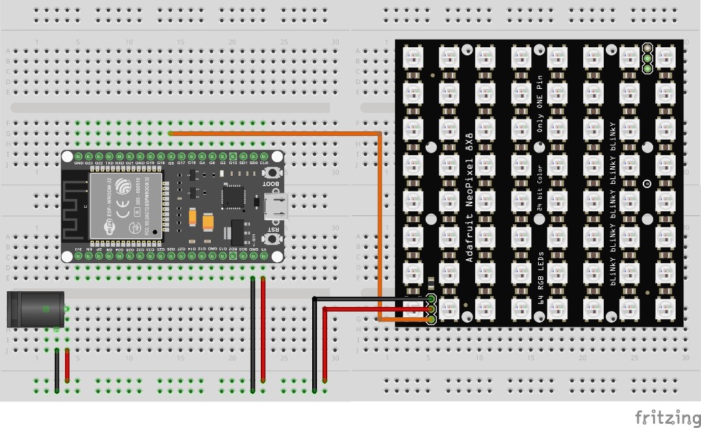
ESP32 DevKit, 8x8 WS2812 / NeoPixel matrix (zig-zag wiring), external 5 V supply, ~330-470 ohm data resistor, jumper wires. Library: Adafruit NeoPixel by Adafruit.
Before power: inspect wiring, confirm supply voltage and ensure all connected circuits share GND.
Libraries for this lesson
In Arduino IDE 2 open Tools → Manage Libraries…. Search by the Library Manager name and install the package by the exact author below. Similar names from other authors can use different APIs and will break the example.
| Include | Library Manager name | Author | Install note |
|---|---|---|---|
Adafruit_NeoPixel.h | Adafruit NeoPixel | Adafruit | Install via Library Manager. Same library as ESP32 Lesson 06. |
What you will do
An 8x8 matrix is 64 NeoPixels in a square. To draw on it you want to say 'column 2, row 1', not 'LED number 13'.
Sketch 1 lights two chosen pixels to check your XY() function. Sketch 2 walks a dot across every row, like reading a page.

A matrix is still a strip
Inside, the 64 LEDs are one long strip numbered 0 to 63, folded into 8 rows. x is the column (0 to 7, left to right). y is the row (0 to 7, top to bottom). XY(x, y) works out the LED number for you.
| Name | Meaning |
|---|---|
| x | Column, 0 to 7, left to right |
| y | Row, 0 to 7, top to bottom |
| XY(x, y) | Our function that gives the LED number |
| show() | Sends the colours to the LEDs |
Zig-zag rows
Most matrices are wired in a zig-zag. Even rows (0, 2, 4, 6) run left to right. Odd rows (1, 3, 5, 7) run right to left.
y % 2 is the remainder when y is divided by 2. It is 0 for even rows and 1 for odd rows, so it tells XY() which way the row runs.
int XY(int x, int y) {
  if (y % 2 == 0) {                   // even row: runs left to right
    return y * 8 + x;
  } else {                            // odd row: runs right to left
    return y * 8 + (7 - x);
  }
}
Power reminder
64 LEDs can draw a lot of current. Use a 5 V supply, connect its GND to the ESP32 GND, keep the data resistor, and keep colour values low.
Wiring and safe build sequence
- Power off before connecting the matrix
- 5 V supply + -> matrix 5 V
- 5 V supply GND -> matrix GND and ESP32 GND
- ESP32 GPIO 5 -> 330-470 ohm -> matrix DIN
- USB powers the ESP32 only
Worked sketch 1: Light two chosen pixels
Download .inoWhat this sketch is for: A red pixel marks the top-left corner (0, 0). A blue pixel should appear at column 2 of row 1. If the blue pixel is near the right-hand edge instead, your matrix starts from a different corner - try turning it around.
#include <Adafruit_NeoPixel.h>                // the NeoPixel library

const int dataPin = 5;                        // the matrix DIN wire is on GPIO 5
const int width = 8;                          // 8 columns
const int height = 8;                         // 8 rows

// describe the matrix: 64 LEDs on one data pin
Adafruit_NeoPixel matrix(width * height, dataPin, NEO_GRB + NEO_KHZ800);

int XY(int x, int y) {                        // turn column x and row y into an LED number
  if (y % 2 == 0) {                           // even row: runs left to right
    return y * width + x;                     // count along from the left
  } else {                                    // odd row: runs right to left
    return y * width + (width - 1 - x);       // count back from the right
  }
}

void setup() {                                // runs once
  matrix.begin();                             // get the matrix ready
  matrix.setPixelColor(XY(0, 0), matrix.Color(60, 0, 0)); // column 0, row 0: red
  matrix.setPixelColor(XY(2, 1), matrix.Color(0, 0, 60)); // column 2, row 1: blue
  matrix.show();                              // send the colours to the matrix
}

void loop() {                                 // nothing to repeat in this sketch
}
How the code works
- Row 1 is an odd row, so it is the real test of the zig-zag.
- return sends the answer back to the line that called XY().
- If the pixels look mirrored, check which corner the DIN wire enters.
Worked sketch 2: Walk a dot across the matrix
Download .inoWhat this sketch is for: Two for loops visit every pixel: each row from top to bottom, and each column from left to right. Thanks to XY(), the dot moves like your eyes reading a page, even though the wiring zig-zags. Match the 5 V supply breadboard below before upload.
#include <Adafruit_NeoPixel.h>                // the NeoPixel library

const int dataPin = 5;                        // the matrix DIN wire is on GPIO 5
const int width = 8;                          // 8 columns
const int height = 8;                         // 8 rows

// describe the matrix: 64 LEDs on one data pin
Adafruit_NeoPixel matrix(width * height, dataPin, NEO_GRB + NEO_KHZ800);

int XY(int x, int y) {                        // turn column x and row y into an LED number
  if (y % 2 == 0) {                           // even row: runs left to right
    return y * width + x;                     // count along from the left
  } else {                                    // odd row: runs right to left
    return y * width + (width - 1 - x);       // count back from the right
  }
}

void setup() {                                // runs once
  matrix.begin();                             // get the matrix ready
}

void loop() {                                 // runs over and over
  for (int y = 0; y < height; y++) {          // each row, top to bottom
    for (int x = 0; x < width; x++) {         // each column, left to right
      matrix.clear();                         // all pixels off (in memory)
      matrix.setPixelColor(XY(x, y), matrix.Color(0, 60, 0)); // this pixel green
      matrix.show();                          // send the colours to the matrix
      delay(80);                              // wait so you can see the dot
    }
  }
}
How the code works
- The outer loop picks a row; the inner loop runs along that row.
- Without XY() the dot would run backwards on every second row.
- Build from the breadboard photo: 8x8 matrix on its own 5 V supply, data on GPIO 5.
Test and record evidence
Practical evidence checklist
Common faults and checks
- Blank matrix: check 5 V, the shared GND, the DIN wire, and that Adafruit NeoPixel is installed.
- Blue pixel on the wrong side, or the dot runs backwards on some rows: your matrix starts from another corner - turn it around, or swap the two return lines in XY().
- Board resets: lower the colour values or use a stronger 5 V supply.
Check your understanding
Q1. How many LEDs are in an 8x8 matrix, and how are they numbered?
Show answer
64, numbered 0 to 63.
Q2. What do x and y mean in XY(x, y)?
Show answer
x is the column and y is the row.
Q3. What is zig-zag wiring?
Show answer
Even rows run left to right; odd rows run right to left.
Q4. What is 3 % 2?
Show answer
1 - the remainder when 3 is divided by 2. So row 3 is an odd row.
Q5. Why write an XY() function?
Show answer
So you can think in columns and rows instead of LED numbers.
Q6. Why keep colour values low?
Show answer
64 LEDs at full white draw a lot of current.
Q7. In sketch 2, which loop picks the row?
Show answer
The outer loop (y).