
E14. Deep Sleep and Power Management
Save battery: put the ESP32 into deep sleep and wake it with a timer, then with a button.
Learning outcomes
- Explain why battery projects sleep most of the time
- Wake the ESP32 from deep sleep with a timer
- Keep a count across sleeps with RTC_DATA_ATTR
- Wake the ESP32 with a button
Parts and preparation
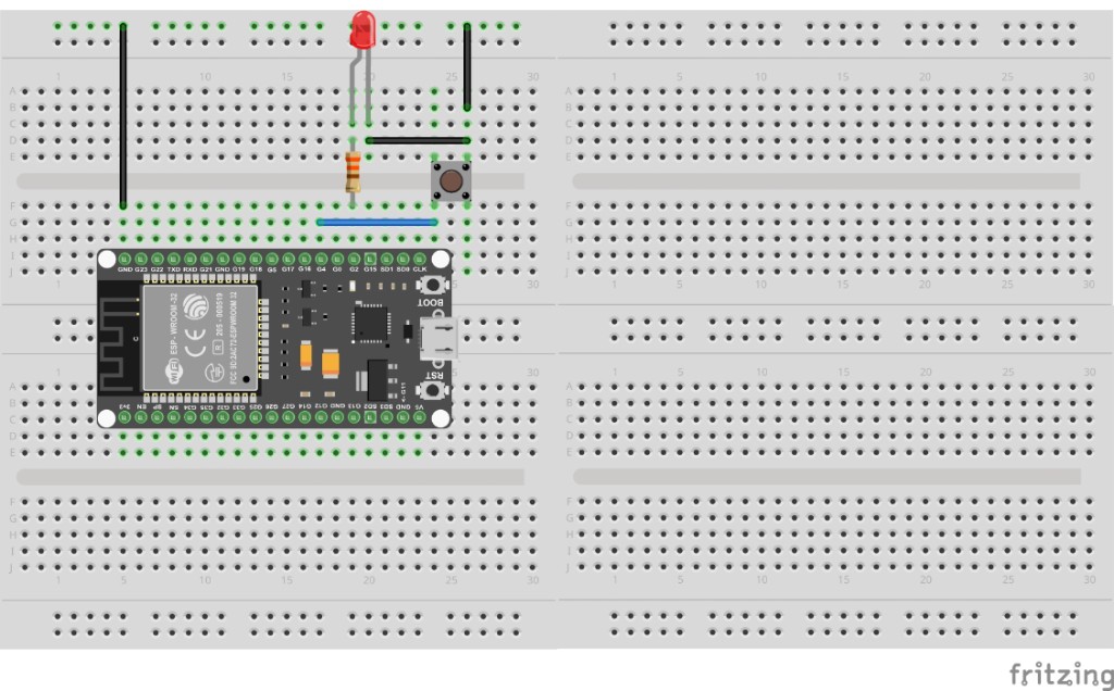
ESP32 DevKit, USB data cable. Sketch 2: push-button on GPIO 4 to GND, and the LED on GPIO 2 (or the on-board LED).
Before power: inspect wiring, confirm supply voltage and ensure all connected circuits share GND.
What you will do
Wi-Fi left on all day empties a battery fast. Battery gadgets wake up, do their job in a moment, and go back to deep sleep.
Sketch 1 sleeps for 5 seconds, wakes, counts how many times it has woken, and sleeps again. Sketch 2 sleeps until you press a button.

Waking restarts the sketch
In deep sleep almost all of the chip switches off. When it wakes, the sketch starts again from setup(), as if you had pressed EN. So the sketch does its work in setup() and then sleeps - loop() is never reached.
Normal variables are lost in deep sleep. Put RTC_DATA_ATTR in front of a variable to keep it - it lives in a small memory that stays powered.
| Kept in | Survives deep sleep? | Survives unplugging? |
|---|---|---|
| A normal variable | No | No |
| An RTC_DATA_ATTR variable | Yes | No |
| Flash, with the Preferences library | Yes | Yes |
Ways to wake up
You choose what wakes the ESP32 before it goes to sleep.
| Wake by | Good for | Command |
|---|---|---|
| Timer | Taking a reading every few minutes | esp_sleep_enable_timer_wakeup() |
| Button or switch | A doorbell or a door sensor | esp_sleep_enable_ext0_wakeup() |
Measuring the saving
A USB current meter will show the current drop during sleep, but not to the tiny datasheet figure: the DevKit's USB chip and power LED stay on. Bare ESP32 modules on batteries save far more.
Wiring and safe build sequence
- Sketch 1: USB only
- Sketch 2: button between GPIO 4 and GND; LED with resistor on GPIO 2 (or the on-board LED)
- Open Serial Monitor at 115200 before the board wakes, to catch the lines
Worked sketch 1: Wake up every 5 seconds
Download .inoWhat this sketch is for: Watch the wake count rise by one every 5 seconds. Unplug USB and plug it back in - the count starts again.
RTC_DATA_ATTR int wakeCount = 0;          // RTC_DATA_ATTR keeps this number during sleep

void setup() {                             // runs at power-on AND every time it wakes
  Serial.begin(115200);                    // start Serial at the ESP32 speed
  delay(500);                              // give the USB link time to start

  wakeCount = wakeCount + 1;               // count this wake-up
  Serial.print("Awake! Wake count: ");     // a label
  Serial.println(wakeCount);               // the count

  Serial.println("Sleeping for 5 seconds"); // say what happens next
  Serial.flush();                          // finish sending before sleeping
  esp_sleep_enable_timer_wakeup(5000000);  // wake after 5,000,000 microseconds = 5 seconds
  esp_deep_sleep_start();                  // sleep now
}

void loop() {                              // never reached - waking restarts setup()
}
How the code works
- The timer counts in microseconds: 1 second is 1,000,000 microseconds.
- Serial.flush() waits until the last line has been sent, so it is not cut off by the sleep.
- Without RTC_DATA_ATTR the count would be 1 every time.
Worked sketch 2: Wake with a button
Download .inoWhat this sketch is for: The LED shows when the ESP32 is awake. It stays on for 2 seconds, then the board sleeps until you press the button. Use the same button and LED wiring as ESP32 Lesson 03.
#include <driver/rtc_io.h>                // commands for the pins that work during sleep

const int ledPin = 2;                      // the LED is on GPIO 2

void setup() {                             // runs at power-on AND every time it wakes
  Serial.begin(115200);                    // start Serial at the ESP32 speed
  pinMode(ledPin, OUTPUT);                 // the LED pin is an output

  digitalWrite(ledPin, HIGH);              // LED on: we are awake
  Serial.println("Awake! Sleeping in 2 seconds - press the button to wake me"); // tell the user
  delay(2000);                             // stay awake for 2 seconds
  Serial.flush();                          // finish sending before sleeping

  rtc_gpio_pullup_en(GPIO_NUM_4);          // keep GPIO 4 pulled HIGH while asleep
  esp_sleep_enable_ext0_wakeup(GPIO_NUM_4, 0); // wake when GPIO 4 goes LOW (button pressed)
  esp_deep_sleep_start();                  // sleep now - the LED goes off
}

void loop() {                              // never reached - waking restarts setup()
}
How the code works
- GPIO_NUM_4 is how the sleep commands write GPIO 4.
- The button pulls GPIO 4 LOW, just like INPUT_PULLUP in ESP32 Lesson 03. rtc_gpio_pullup_en keeps the pull-up on during sleep.
- Only some pins can wake the ESP32. GPIO 4 is one of them.
Test and record evidence
Practical evidence checklist
Common faults and checks
- Count always 1: check RTC_DATA_ATTR is in front of the variable. Unplugging USB also resets it.
- Lines cut short or missing: keep Serial.flush() before esp_deep_sleep_start().
- Upload fails while it sleeps: press and hold BOOT, start the upload, release BOOT when writing starts.
- Button does not wake it: check the button is on GPIO 4 and GND.
Check your understanding
Q1. Why do battery gadgets use deep sleep?
Show answer
Staying awake with Wi-Fi on uses up the battery quickly.
Q2. Where does the sketch start after waking from deep sleep?
Show answer
At the beginning of setup().
Q3. What does RTC_DATA_ATTR do?
Show answer
Keeps a variable's value during deep sleep.
Q4. Does an RTC_DATA_ATTR variable survive unplugging?
Show answer
No.
Q5. How many microseconds are in 5 seconds?
Show answer
5,000,000.
Q6. Why call Serial.flush() before sleeping?
Show answer
So the last line finishes sending before the chip sleeps.
Q7. Name two things that can wake the ESP32.
Show answer
A timer and a button (pin).