
PWM & Fading
Dim an LED with analogWrite, fade it up and down, drive the brightness from a knob, and fade without blocking the sketch.
Switching fast to fake the in-between
A digital pin is only ever fully on or fully off. PWM switches it on and off about 490 times a second, and the fraction of the time it spends HIGH - the duty cycle - decides how bright an LED looks.
analogWrite(pin, duty) takes a duty from 0 (off) to 255 (fully on). It only works on the pins marked ~ on the board: 3, 5, 6, 9, 10 and 11. On any other pin the simulator warns you, exactly as the real board would misbehave.
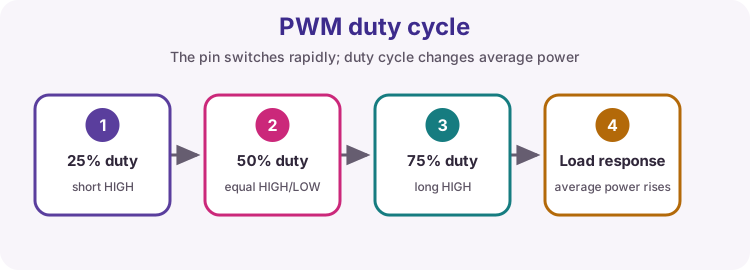
Four brightness steps
Watch the virtual LED: its glow follows the duty value, not just on and off.
Half brightness
Set the LED on pin 9 to half brightness (duty 128) and leave it there.
Three brightness steps
Step the LED through 64 → 128 → 255, 400 ms at each level, over and over. No other brightness values.
Fade up
Fade the LED from off to full and start again: step the duty from 0 to 255 in steps of 5, waiting 20 ms at each step. Use a for loop.
Breathing LED
Now fade up and back down, so the LED breathes. Keep the same steps of 5 and 20 ms waits: up from 0 to 255, then down from 255 to 0.
The knob dims the LED
Put Chapter 9 and this chapter together: read the potentiometer on A0 (0-1023) and use it to set the LED brightness (0-255). map() does the scaling. The test turns the knob while your sketch runs.
Fade without blocking
All that delay(20) means the sketch can do nothing else while it fades. Here the onboard LED must keep blinking every 500 ms - its timer is already written.
Fade pin 9 with a millis() timer instead: every 10 ms add 5 to the duty, and go back to 0 after 255. No delay().
Try it on a real Uno
Put an LED and a 330 Ω resistor on pin 9 - it must be a ~ pin - and upload Breathing LED. Move it to pin 8 and upload again: it only switches fully on and off, which is what the simulator warns about.
Then add the potentiometer from Lesson 10 and upload The knob dims the LED.