World-class language, types, snprintf, I/O and circuit reference for this course. Read matching sections before practical lessons.
About this reference
Use this page as a lookup while you build - language, types, snprintf, I/O, timing and starter circuits. Practical lessons still own wiring and full sketches. When a lesson says Read this first, jump to the linked topic below.
note
How to use this reference
Topics here cover Arduino sketch language, data types, snprintf text formatting, core I/O functions, timing, Serial, and the starter circuit ideas used early in the course. Hardware beyond this scope (I2C, DHT, RTC, ultrasonic, IR, RFID and similar) is taught in the dedicated lessons for those modules - those lessons still link here for language tools such as snprintf.
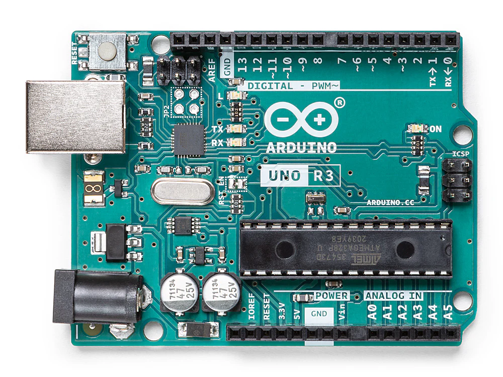
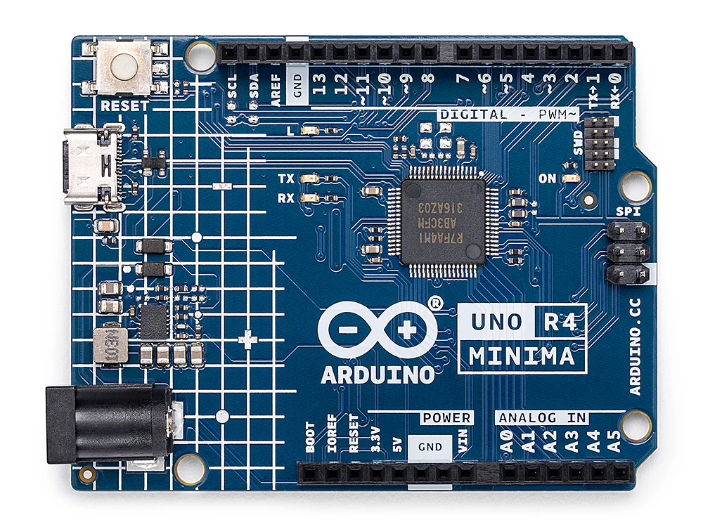
Uno Rev3 and UNO R4 Minima board photos are official Arduino® images from store.arduino.cc (CC BY-SA). Arduino® is a trademark of Arduino S.r.l.
Board guide: Uno R3 and R4 Minima
Know the board under your hands: power pins, I/O, on-board LEDs, and what changes if you use an Uno R4 Minima. This course defaults to Uno R3.
table
Arduino Uno R3
Classic Uno Rev3 with ATmega328P, USB-B, and 5 V logic. Default board for this course. Product overview: Arduino store - Uno Rev3 (store.arduino.cc/products/arduino-uno-rev3).
Same Uno form factor and 5 V class, Renesas RA4M1 MCU, USB-C, more memory and extras (DAC, RTC, CAN, HID). Select “UNO R4 Minima” in the IDE. Product overview: Arduino store - UNO R4 Minima (store.arduino.cc/products/uno-r4-minima).
Every Uno sketch needs a clear shape: declarations, one-time setup, then a repeating loop. Syntax rules keep the compiler happy; a shared style keeps sketches readable and consistent with Arduino examples.
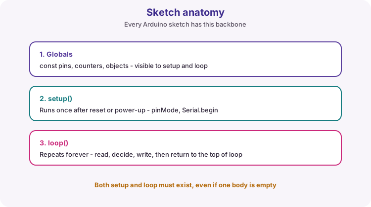
Global declarations (constants, variables, objects) usually sit above setup. setup() runs once after reset or power-up for configuration such as pinMode and Serial.begin. loop() then runs for the life of the program: read inputs, decide, write outputs. Both functions must exist even if one body is empty.
Globals, setup once, loop forever - the sketch backbone.
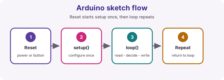
Reset to repeating loop
After reset or power-up, setup runs once, then loop repeats until power is removed.
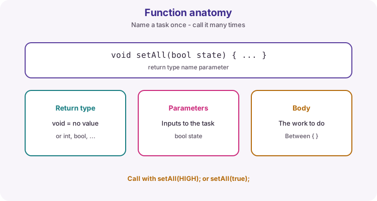
A function packages work behind a clear name. Parts: return type, name, parameter list, body. void means no return value - the function only performs an action. Parameters are inputs. Keep functions short so each one is easy to test and reuse.
Return type, name, parameters, body. Call the name whenever you need the task.
A shared style keeps sketches organised, easy to mark, and closer to official Arduino examples and libraries. This course covers naming, braces, spacing and pin constants. Follow them unless a brief says otherwise - markers and teammates should recognise the shape of your code.
Define pin numbers once at the top of the sketch with const int (preferred) or #define. Never scatter raw “magic numbers” through pinMode, digitalWrite or analogRead calls-changing a wire then means hunting every occurrence.
Tip: Name the role, not only the number: BUTTON_PIN is clearer than PIN2.
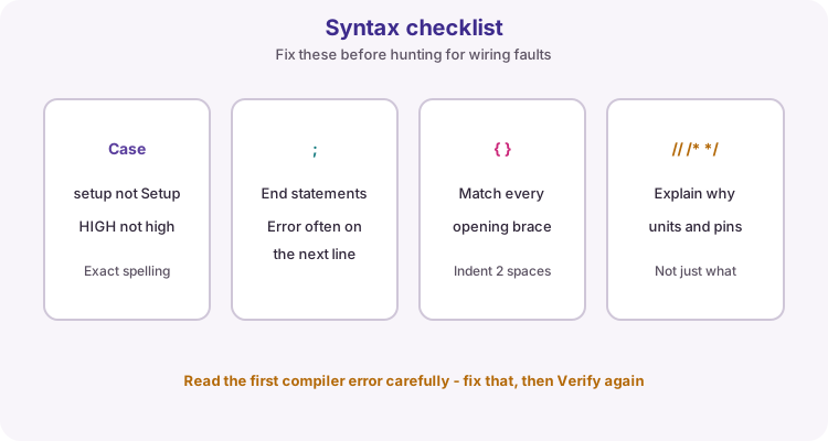
Most statements end with a semicolon. Missing semicolons are a common compile error and the compiler may report the problem on the next line. Do not put a semicolon immediately after if (...), for (...), or while (...) unless you intentionally want an empty statement.
Watch out: if (pressed); { ... } is a classic bug - the semicolon ends the if, so the braces always run.
Comments are ignored by the compiler. Use // for a single-line comment. Use /* ... */ for a multi-line block comment. Write comments that explain intent, units, pin roles and safety assumptions - not only what the next line obviously does.
Case, semicolons, braces, comments - fix the first compiler error, then Verify again.
Choose a type that fits the range you need, name values clearly, keep scope narrow, and know which snprintf format code matches each type.
concept
Variables
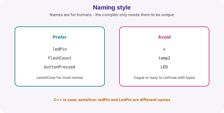
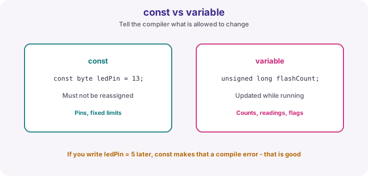
A variable names stored data the program can read and change. Prefer clear camelCase names such as sensorValue. Use const for pin numbers and other values that must not change after they are set. See Naming conventions for the full style table.
const for fixed pins and limits. Variables for values that update while running.
Declare before use: type, name, and optional initial value. Declaration allocates storage and tells the compiler how to interpret the bits. Initialise values you depend on - uninitialised locals can hold garbage.
Part
Meaning
Type
How the bits are interpreted (byte, int, ...)
Name
How you refer to the value in code
Initial value
Starting contents (recommended)
concept
Variable scope
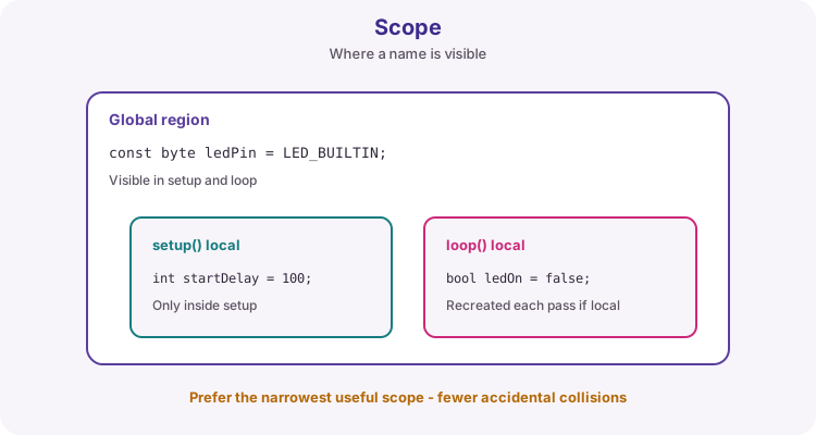
Scope is where a name is visible. Globals above setup are visible to many functions. Locals inside a function or block exist only there. Prefer the narrowest useful scope so lifetimes stay clear and names do not collide. A local bool ledOn = false; inside loop is recreated every pass - bad if you expected it to remember a toggle.
Globals are shared. Locals live only inside their braces.type
Type: byte
byte pin = 9; // 0 … 255
8-bit unsigned integer (0 to 255). Useful for pin numbers and small counters. Cannot store fractions. In snprintf, byte promotes and is usually printed with %d.
Tip: Pin numbers fit in byte. Prefer const byte ledPin = 9; then print with %d in snprintf.
type
Type: int
int x; // about -32768 … 32767 on Uno
On the classic Uno (ATmega328P), int is 16-bit signed (about -32768 to 32767). Everyday integer type for many sketches and analogRead results. Watch for overflow. Format with %d or %i; use %02d when you need zero-padding.
long x;
unsignedlong t = millis(); // print with %lu
Wider integers (32-bit on the Uno). Use long or unsigned long when values may exceed int range. millis() returns unsigned long - store timestamps in unsigned long and format with %lu (signed long uses %ld).
Approximate decimal numbers for voltages and averages. Integer division discards the remainder unless at least one operand is floating-point (for example total / 4.0). Serial.println(float) works; inside snprintf on AVR Uno prefer dtostrf then %s (see Floats with dtostrf).
Stores true or false. Ideal for flags, LED state, and named conditions. In Serial or snprintf you can print it with %d (shows 0 or 1), or print a label yourself.
Tip: Name booleans as questions or states: aPressed, alarmActive - not flag or temp.
Holds one character (one byte). Character literals use single quotes: '1', 'A', '\n'. A sequence of characters in a char array forms a C string when it ends with a null terminator. Format with %c for one character, or %s for a whole C string.
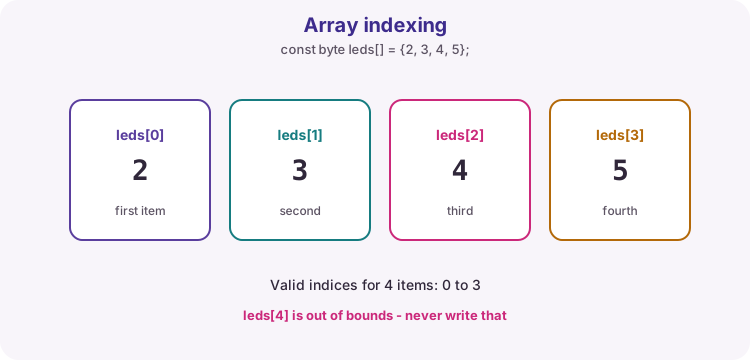
An array holds several values of one type under one name, accessed by index. The first index is 0. For four items, valid indices are 0-3. Never read or write past the last valid index - that is undefined behaviour and looks like random bugs.
Four items means indices 0-3. leds[4] does not exist.
Bounds trap
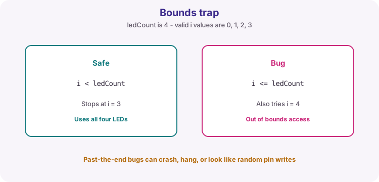
The classic off-by-one error is i <= ledCount instead of i < ledCount.
i < ledCount stops at the last valid index.
Tip: const byte ledCount = sizeof(leds) / sizeof(leds[0]); keeps the length matched to the array.
Compose fixed-width text for Serial, LCD and logs. Learn char buffers, snprintf format codes matched to data types, zero-padding, and the AVR float workaround with dtostrf.
concept
C strings and char buffers
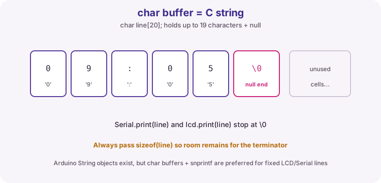
char line[20]; // up to 19 chars + '\0'
A C string is a char array that ends with a null terminator (byte value 0, written '\0'). Serial.print(line) and lcd.print(line) stop at that terminator.
Declare a buffer large enough for the longest text you will write, including '\0'. Example: HH:MM:SS needs 8 characters plus '\0', so char line[9]; is the minimum - course sketches often use a little spare room (16 or 24) for labels.
Text lives in the array; '\0' marks the end. Leave space for it.
Buffer habits
sizeofPass the size
Always pass sizeof(line) to snprintf so the library knows the limit.
StringArduino String
String objects are convenient but fragment scarce SRAM on Uno. Prefer char buffers for fixed LCD/Serial lines in this course.
ClearOptional start
You do not usually need to clear the buffer first; snprintf overwrites from the start and writes a new '\0'.
Tip: If text looks truncated, the buffer is too small or you passed the wrong size. Count characters + 1 for '\0'.
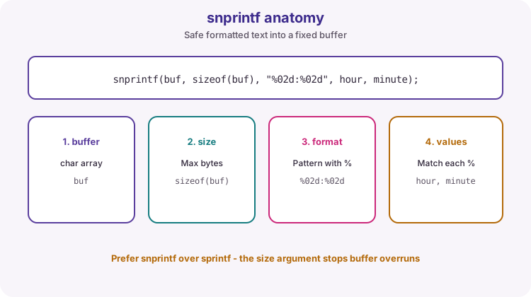
snprintf writes formatted text into a char buffer. Unlike sprintf, it takes the buffer size and will not write past the end (it still needs a correct size argument from you).
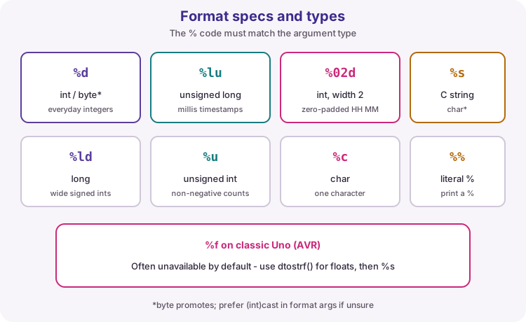
Arguments after the format string fill each % placeholder in order. The format code must match the type you pass.
Buffer, size, format, values. Keep the % codes and arguments in lockstep.
Specifier
Pass this type
Example result
%d or %i
int (byte promotes)
42
%u
unsigned int
400
%ld
long
-100000
%lu
unsigned long
millis value
%02d
int, width 2, zero-pad
09 from 9
%04d
int, width 4, zero-pad
2026
%c
char
A
%s
const char* / char[]
OK
%%
(none)
literal %
%f
float (often unavailable on AVR)
Prefer dtostrf
Match % codes to datatypes
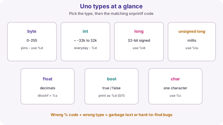
This is the rule students must memorise: every % code consumes one argument of the matching type. Mismatch is undefined behaviour - Serial may show nonsense without a compile error.
Pick the code from the type you already chose for the variable.
You stored
Format with
Avoid
int hour
%d or %02d
%lu, %f
unsigned long t = millis()
%lu
%d (truncates / wrong)
long distance
%ld
%d on large values
char cmd
%c
%s
char msg[] = "OK"
%s
%c
float volts
dtostrf + %s
%d, bare %f on Uno
bool ok
%d (0/1) or if/else labels
%s with bool
Watch out: Compilers may not catch format/type mismatches in snprintf. Wrong pairs are a silent runtime bug.
Width and zero-padding
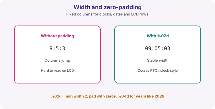
%02d means: print an integer in at least 2 columns, pad with zeros on the left. That keeps clock and date columns stable on a 16x2 LCD when hours go from 9 to 10.
%04d is the usual year width. A plain %d is fine when width does not matter.
Padding stops the display from jumping as digits change.
snprintf returns the number of characters that would have been written (excluding '\0'), or a negative value on encoding error. If the return value is greater than or equal to the buffer size, the output was truncated.
Always pass sizeof(buffer) for array buffers. Never pass a guessed number that is larger than the array. Prefer snprintf to sprintf so a size mistake is less likely to smash neighbouring memory.
Watch out: sprintf has no size limit. One oversized line can corrupt variables and crash the board. Use snprintf.
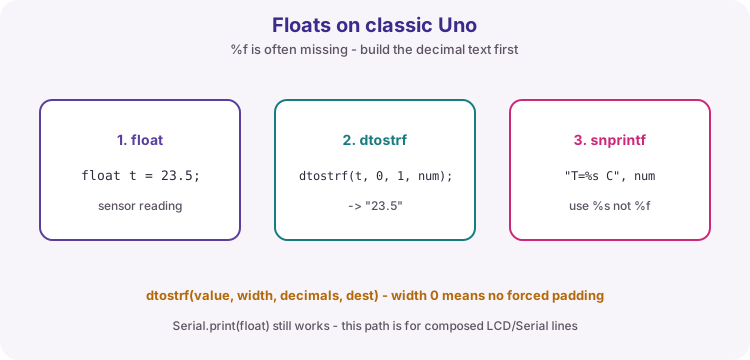
On the classic Uno (AVR), printf-family float support (%f) is often disabled to save flash. Serial.print(23.5) still works for a lone float, but composing a full line with snprintf needs another path.
dtostrf(value, width, decimals, buffer) writes the decimal text into a char buffer. Then insert it with %s. width 0 means no forced character count; decimals is digits after the point.
Float -> dtostrf -> char[] -> snprintf with %s.
dtostrf arguments
valueThe float
The number to convert.
widthMinimum width
Use 0 unless you want space/zero padding in the numeric field itself.
// Clock / RTC linesnprintf(line, sizeof(line), "%02d:%02d:%02d", h, m, s);
// Date and time stampsnprintf(stamp, sizeof(stamp), "%04d-%02d-%02d %02d:%02d:%02d",
year, month, day, h, m, s);
// Labelled integersnprintf(line, sizeof(line), "raw=%d", raw);
// millis uptimesnprintf(line, sizeof(line), "t=%lu ms", millis());
Copy these shapes into LCD, Serial and SD log sketches. Change only the buffer size, labels and variable names.
Need
Pattern
Stable clock
%02d:%02d:%02d
Calendar date
%02d/%02d/%04d or %04d-%02d-%02d
ADC raw
raw=%d
millis
t=%lu ms
Float in a line
dtostrf then T=%s C
Status word
%s with a const char* label
Tip: After snprintf, print once: Serial.println(line); or lcd.print(line); - do not rebuild the string with many separate print calls if you need fixed columns.
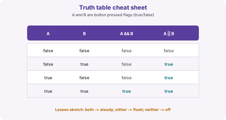
Calculate, compare and choose which statements run - the same toolkit as Lesson 05. One wrong operator (= vs ==) is a classic bug. Use the figures and truth table here as a desk reference while you build.
syntax
Arithmetic operators
a + b    // add
a - b    // subtract
a * b    // multiply
a / b    // divide
a % b    // remainder (modulo)

x = x + 1;
x += 1;   // same idea, shorter
i++;      // add 1 to i
i--;      // subtract 1 from i
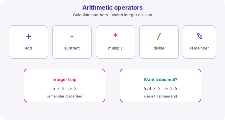
Use + - * / and % to calculate with numbers in variables or literals. % (modulo) is the remainder after division - handy for wrapping counters and simple blink patterns such as millis() / 250 % 2.
Integer trap: when both operands are integers, / discards the fraction. 5 / 2 is 2. Write 5.0 / 2 (or cast) when you need 2.5.
Five arithmetic operators. Integer division drops the remainder unless you use a float.
Basic operators
+Addition
Adds two numbers. Example: 3 + 2 = 5.
-Subtraction
Subtracts the right number from the left. Example: 10 - 4 = 6.
*Multiplication
Multiplies two numbers. Example: 3 * 4 = 12.
/Division
Divides the left number by the right. With whole numbers (int), the fraction is dropped: 7 / 2 = 3, not 3.5. Use a decimal such as 7.0 / 2 if you need 3.5.
%Modulo (remainder)
Answers: after dividing, what is left over? Example: 10 % 3 = 1, because 3 fits into 10 three times (9) with 1 left. Odd/even checks: 7 % 2 = 1 (odd), 8 % 2 = 0 (even). Also useful for wrapping counters and alternating patterns.
Compound and shortcut operators
+= -= *= /=Compound assignment
Update a variable using its current value. x += 1 means take x, add 1, and store the result back in x (same as x = x + 1). Likewise x -= 2, x *= 2, or x /= 2.
++ --Increment / decrement
Shortcuts to add or subtract 1. i++ adds 1 to i; i-- subtracts 1. Common in for loops when counting one step at a time.
Operator
Meaning
Example
+
Add
3 + 2 -> 5
-
Subtract
3 - 2 -> 1
*
Multiply
3 * 2 -> 6
/
Divide
5 / 2 -> 2 (ints)
%
Remainder
5 % 2 -> 1
Tip: If you need a decimal result from division, make at least one value floating-point (for example total / 4.0), otherwise int maths drops the fraction.
a == b   // equal to
a != b   // not equal to
a <  b   // less than
a <= b   // less than or equal
a >  b   // greater than
a >= b   // greater than or equal
Comparison operators ask a yes/no question about two values. The answer is true or false, and is usually used inside if or a loop condition.
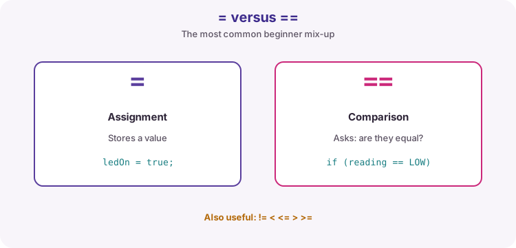
= stores a value. == asks whether two values are equal. Writing if (x = 1) by mistake assigns 1 to x and often looks always true - a classic bug.
= stores. == compares. Memorise this before hunting wiring faults.
Comparisons
==Equal to
True only when both sides are the same. Example: sensorValue == 0 is true only when sensorValue is exactly 0.
!=Not equal to
True when the sides differ. Example: buttonState != HIGH is true when the button is not HIGH.
<Less than
True when the left value is smaller than the right.
>Greater than
True when the left value is larger than the right.
<=Less than or equal
True when the left value is smaller than or the same as the right.
>=Greater than or equal
True when the left value is larger than or the same as the right. Example: reading >= 512 is true in the upper half of the 0-1023 analogue range.
Assignment vs comparison
=Assign
Stores a value into a variable. state = HIGH puts HIGH into state.
==Compare
Checks whether two values are already equal, without changing them. state == HIGH asks: is state already HIGH?
Watch out: if (state = HIGH) assigns HIGH and is almost always a mistake. The condition becomes true because the assigned value is HIGH. Use == for comparisons.
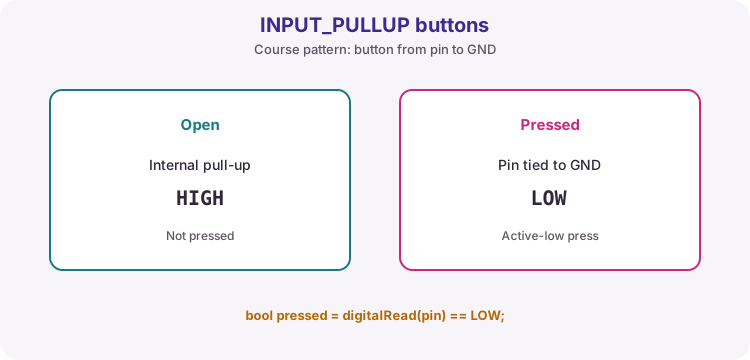
pinMode uses these modes. INPUT is high-impedance (can float if nothing drives the pin). OUTPUT drives the pin as a low-impedance output. INPUT_PULLUP enables the chip's internal pull-up - the usual course pattern for a button to GND.
Course buttons: pinMode INPUT_PULLUP, switch to GND, pressed == LOW.
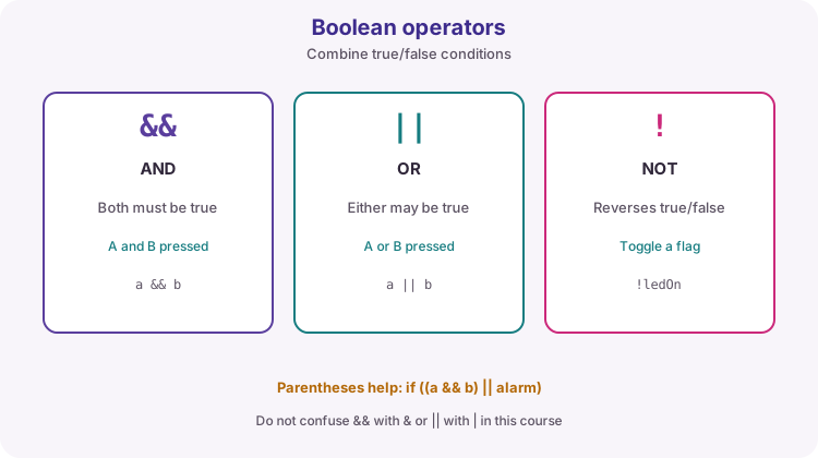
if (aPressed && bPressed) {
// both - steady
} elseif (aPressed || bPressed) {
// either - flash
} else {
// neither - off
}
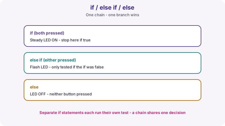
An if chain tests conditions in order. Only the first true branch runs; the rest are skipped. else covers whatever is left when no earlier test matched.
Separate if statements are different: each is tested on its own, so more than one body can run. Use a chain when outcomes must be mutually exclusive (steady vs flash vs off).
One chain, one winner. Order matters: test both before either.
Chain vs separate ifs
chainif / else if / else
One winner. Use when outcomes must not overlap.
separateif; if; if;
Each test runs. Several bodies can execute.
Order tip (Lesson 05)
both firstSpecific before general
Test aPressed && bPressed before aPressed || bPressed, or both-pressed will flash instead of staying steady.
Watch out: if (state = HIGH) assigns HIGH and is almost always a mistake. Use == for comparisons.
Decision flow pattern
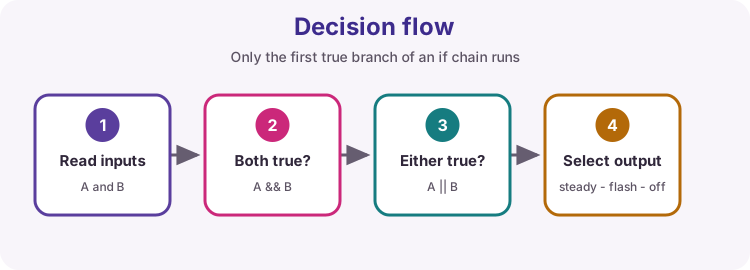
Read inputs into clear bool names, then choose one output action. This is the backbone of Lesson 05 and most later control sketches.
Read -> test both -> test either -> select steady / flash / off.
Tip: millis() / 250 % 2 flashes without delay() so loop stays responsive while a button is held.
This is the Lesson 05 control pattern in reference form. INPUT_PULLUP buttons to GND make pressed == LOW. Both pressed: steady on. Exactly one: flash with millis modulo. Neither: off.
Copy the shape - clear bool names, specific test first, one output choice - into later projects.
Same decision flow as the Lesson 05 worked sketch.
Inputs
LED behaviour
Neither pressed
Off
Exactly one pressed
Flashing
Both pressed
Steady on
Tip: Build and mark this in Lesson 05. Return here when a later if-chain feels messy.
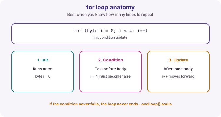
A for header has three parts separated by semicolons: initialisation, condition and update.
Initialisation runs once. The condition is tested before each body pass - if false, the loop ends. After the body, the update runs (often i++), then the condition is tested again. Use for when the count is known: walk every LED, repeat N times, scan an array.
Init once, test the condition, run the body, update, repeat until the test fails.
Parts of for (...)
initInitialisation
Runs once - usually byte i = 0.
conditionTest
Must eventually become false - usually i < count.
updateChange
After each body - usually i++.
Watch out: Use i < ledCount, not i <= ledCount, or you walk one past the last array index.
while (condition) { /* … */ }

do {
  /* … */
} while (condition);
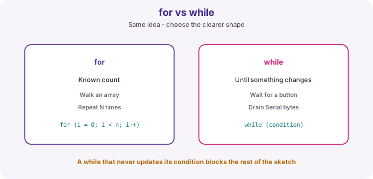
while (condition) repeats as long as the condition stays true. It suits waiting until a button releases, draining Serial bytes, or looping until a flag clears.
Danger: if nothing inside the body can make the condition false, the rest of loop() never runs. do/while runs the body at least once, then tests at the end.
for = known count. while = until something changes.
Watch out: A while that never updates its condition blocks buttons, Serial and every other task.
Configure a pin as INPUT, OUTPUT or INPUT_PULLUP in setup. Set modes explicitly even though pins often default toward inputs. Design for about 20 mA or less per I/O on the Uno; 40 mA is an absolute maximum, not a normal target.
Watch out: Short circuits or overloads on OUTPUT pins can damage the microcontroller.
Active-low buttons and pull-ups
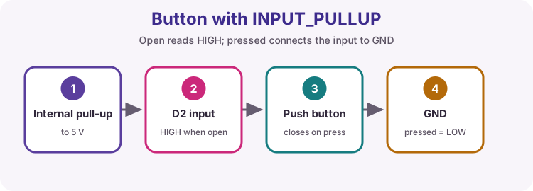
Most course button examples use INPUT_PULLUP and a switch to GND. That is active-low: pressed connects the pin to 0 V. Always write if (digitalRead(pin) == LOW) when you mean “pressed” in that wiring style.
Open reads HIGH; pressed connects the input to GND.
Switch
Pin reads
Meaning (INPUT_PULLUP to GND)
Open (not pressed)
HIGH (~5 V)
Released - pull-up holds the pin high
Closed (pressed)
LOW (~0 V)
Pressed - pin shorted to GND
Tip: Active-high is the opposite idea: a button that pulls the pin up to 5 V when pressed, usually with an external pull-down. Know which style you built before you write the if test.
Returns HIGH or LOW from a digital pin. With INPUT_PULLUP and a button to GND: open reads HIGH, pressed reads LOW (active-low). Always document which polarity your wiring uses before writing the if test.
Active-low press: compare to LOW when using INPUT_PULLUP.
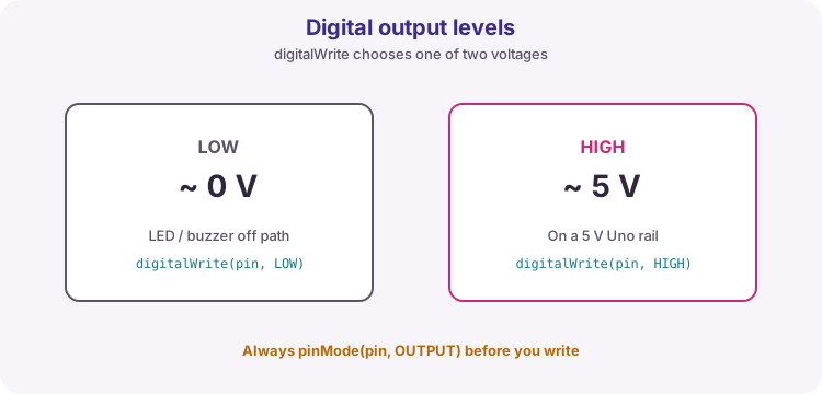
Drive an OUTPUT pin high or low after pinMode(pin, OUTPUT). On a 5 V Uno, HIGH is about 5 V and LOW about 0 V. Use for LEDs (with series resistor), logic inputs, and similar loads - not motors or relays without a driver.
OUTPUT pins switch between roughly 0 V and 5 V on a Uno.
Watch out: Always set pinMode OUTPUT before digitalWrite. Stay within about 20 mA per pin.
Read voltages with the ADC; fake analogue drive with pulse-width modulation on ~ pins.
api
analogRead()
int reading = analogRead(A0); // 0 … 1023
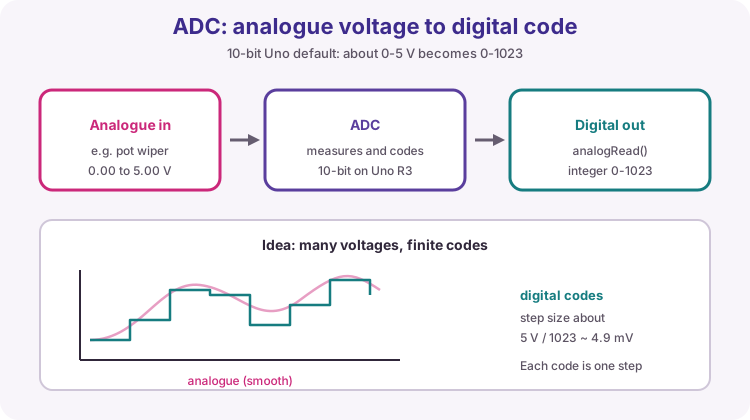
10-bit ADC on A0-A5. With the default 5 V reference, 0 is about 0 V and 1023 is about 5 V (about 4.9 mV per count). Convert with V = reading * 5.0 / 1023.0 using a float operand. Pins used only as ADC inputs do not need pinMode(OUTPUT).
analogRead returns a code, not volts. Convert when you need voltage.
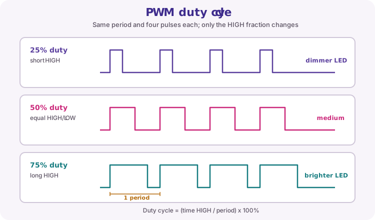
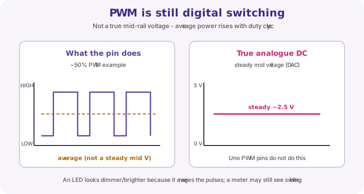
Hardware PWM on pins marked ~ (Uno: 3, 5, 6, 9, 10, 11). value 0 is fully off, 255 fully on; values between set duty cycle. PWM is a fast digital pulse train - not a true DC analogue voltage - but many loads respond to average power.
Duty cycle changes average power. Use a ~ pin with analogWrite.
Schedule work without freezing the sketch, print and receive over USB Serial, and compose fixed lines with snprintf when labels and padding matter.
api
delay()
delay(ms);
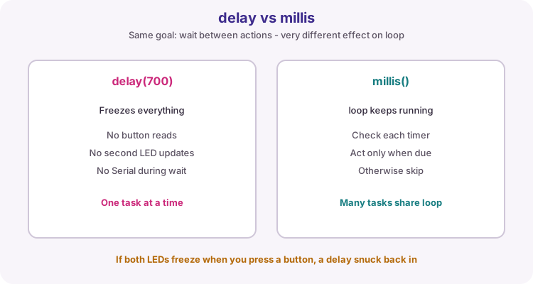
Pauses the sketch for ms milliseconds. Simple for first demos, but nothing else runs during delay - buttons, Serial and other LEDs wait. Prefer millis-based timing when several tasks must stay responsive.
delay freezes everything. millis lets other work continue between events.
Tip: If a button feels dead while an LED blinks with delay(), switch that blink to millis().
unsignedlongnow = millis();
if (now - last >= interval) {
last = now;
// do work
}
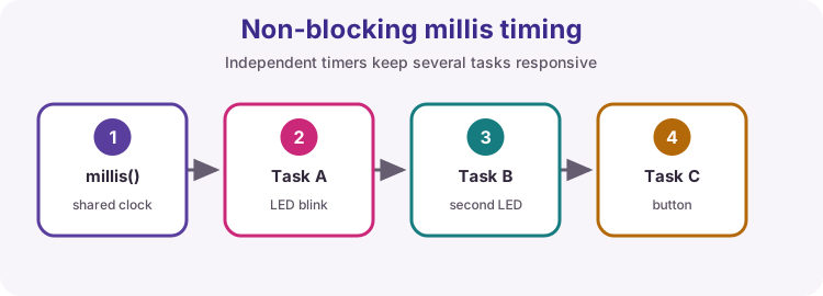
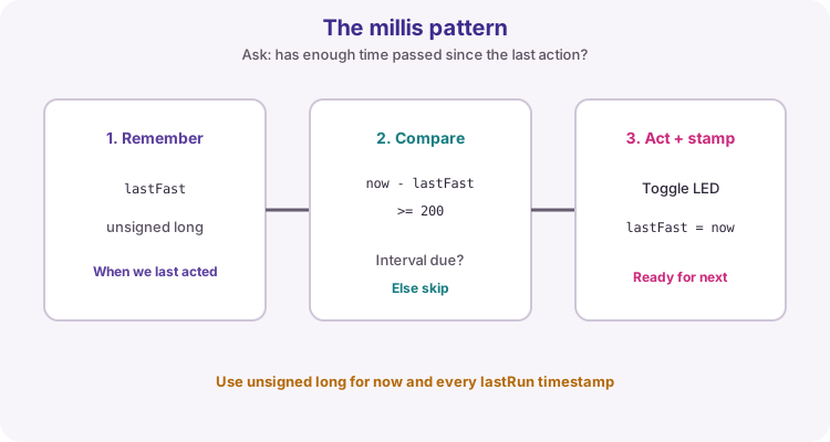
Milliseconds since start, as unsigned long. Save a start time; when millis() - start >= interval, run the action and update start. Overflow after many days is fine when both values are unsigned long. Give each independent task its own timestamp.
Each task keeps its own last-run time. loop stays free between events.
Tip: Store timestamps in unsigned long. Format with snprintf using %lu when you print them.
Interval pattern
Copy this shape for every independent timed task.
if (millis() - last >= interval) { last = millis(); /* work */ }
min(a, b) and max(a, b) return the smaller or larger value - useful for clamping. randomSeed sets the pseudo-random sequence (often millis() or analogRead on a floating pin). random(min, max) returns a value in the requested range for variation in demos.
Call
Role
min(a, b)
Smaller of two values
max(a, b)
Larger of two values
randomSeed(seed)
Start the sequence
random(min, max)
Value in range
api
Serial.begin() and Serial.println()
Serial.begin(9600);
Serial.println(value);
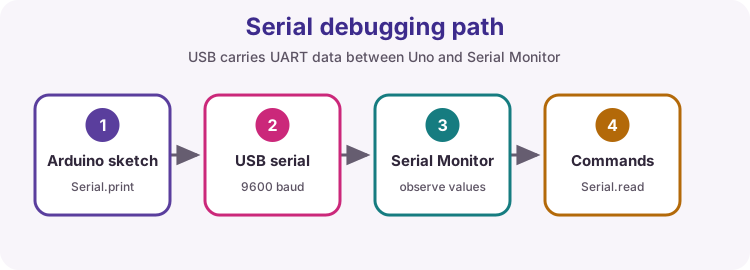
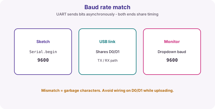
Opens USB serial (9600 is common for learning) and prints a line to the Serial Monitor. On the Uno, D0 (RX) and D1 (TX) are reserved for that link. Match Monitor baud to begin; use a USB data cable.
println adds a line ending; print does not. For multi-field padded lines, build with snprintf then println the buffer.
Sketch <-> USB serial <-> Serial Monitor. Match baud on both ends.
Baud rate must match
Serial.begin(9600) and the Monitor dropdown must show the same number or you get garbage text.
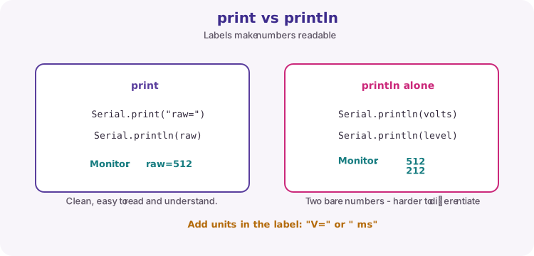
Serial.print("raw=");
Serial.println(raw);
Serial.write(byteValue);  // one raw byte
print continues on the same line; println adds a line ending. Label values so the Monitor is readable. write sends a raw byte - useful for binary protocols, not everyday student debugging.
For a composed line with several fields and padding, prefer snprintf into a buffer, then Serial.println(buffer).
Labels turn a stream of digits into something you can trust at a glance.
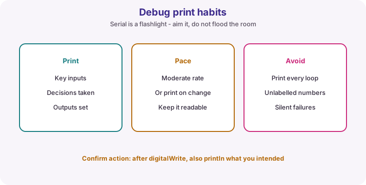
Debug print habits
Print key inputs, decisions and outputs at a readable rate - not every loop pass.
Aim the flashlight. Print on change or at a calm rate.
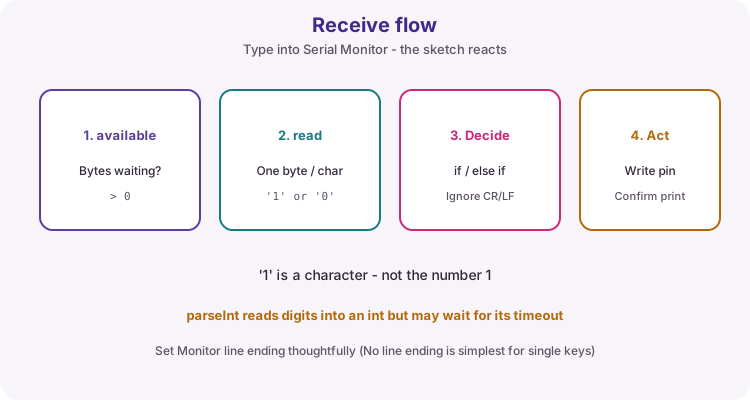
if (Serial.available() > 0) {
  char c = Serial.read();
  // act on c
}
available() reports how many bytes wait in the receive buffer. read() takes one byte. Compare characters with quotes ('1'), not bare numbers. Ignore '\n' and '\r' when you only care about command keys. parseInt() can wait for digits or a timeout - use carefully inside loop().
available -> read -> decide -> act. Confirm with a println.
Starter circuit ideas used across the course - LED, button, drivers, PWM, dividers and servo. Each note pairs a figure with wiring rules; full builds live in the linked practical lessons.
circuit
Digital output (LED)
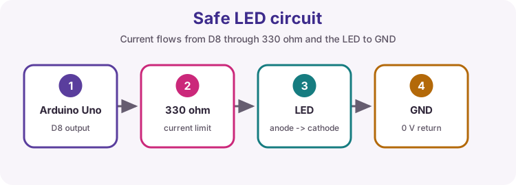
Drive an LED from a digital OUTPUT through a series resistor to GND (anode toward the pin via resistor, cathode to GND for the usual course wiring). This is the hello-world hardware path for Lessons 01, 03 and 07.
Never omit the resistor unless the board already limits current on that path (for example the onboard LED behind LED_BUILTIN).
Pin -> resistor -> LED anode; cathode -> GND.
Item
Course habit
Resistor
Often 330 ohm for a 5 V red LED ~10 mA
pinMode
OUTPUT before digitalWrite
Polarity
Long LED leg is usually the anode
Onboard LED
LED_BUILTIN / pin 13 already has a resistor
Watch out: A bare LED across 5 V can overcurrent a pin. Always calculate or use a safe standard value such as 330 ohm.
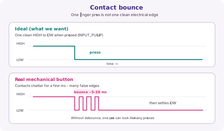
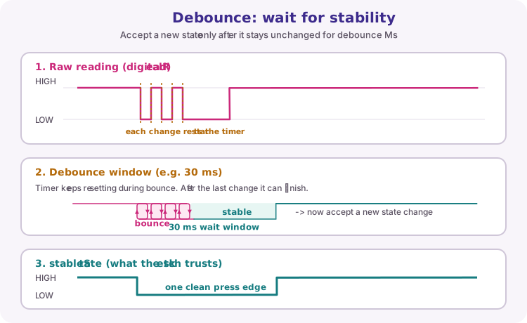
Two-state input. Course style: pinMode INPUT_PULLUP and a switch between the pin and GND. Open reads HIGH; pressed reads LOW (active-low). Mechanical contacts bounce for a few milliseconds - debounce in software for reliable counts (Lesson 08).
Button from pin to GND; internal pull-up holds open inputs HIGH.
Contact bounce
One physical press can look like many edges if you react to every raw change.
Ideal: one clean edge. Real button: chatter, then stable LOW.
Software debounce idea
Accept a new state only after the raw reading stays unchanged for about 20-50 ms.
Restart the timer on every raw change. Only a full stable window updates stableState.
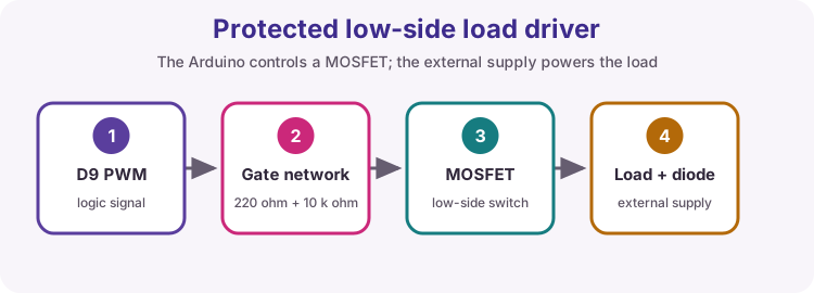
Uno pins cannot safely drive motors, relays, solenoids or heaters directly. Use a transistor or MOSFET as a low-side switch (or a driver module), an external supply sized for the load, common GND with the Uno, and a flyback diode across inductive coils.
Logic pin controls a switch. The load uses its own supply and a flyback diode.
Need
Why
Driver / transistor
Pin current and voltage are limited
External supply
Motors need amps the Uno USB rail cannot give
Common GND
Shared reference between logic and load supply
Flyback diode
Inductive kick when switching coils off
Watch out: Never power a motor from an I/O pin. Shared GND is mandatory between Arduino and the load supply.
Vary duty cycle with analogWrite on a PWM-capable (~) pin to dim an LED or set motor-enable speed on a driver. PWM is a fast digital pulse train, not a smooth DC voltage - many loads still respond to average power.
Higher duty cycle means more average power.
Item
Uno habit
Pins
D3, D5, D6, D9, D10, D11 (~)
Range
0 (off) to 255 (full on)
LED
Still use a series resistor
Motor
PWM into a driver enable / input - not the motor coil alone
PWM versus true analogue
analogWrite does not create a laboratory DC voltage. It pulses. Filtering or the load's inertia often makes that feel smooth.
PWM averages; true analogue holds a steady voltage.
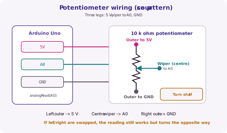
A potentiometer is an adjustable voltage divider: one outer leg to 5 V, the other to GND, wiper to an analogue pin. analogRead returns 0-1023 for position or setpoint control. Measure the 5 V rail if you need accurate volts rather than relative position.
Outer legs to 5 V and GND. Centre wiper to A0. Turn the shaft to change analogRead.
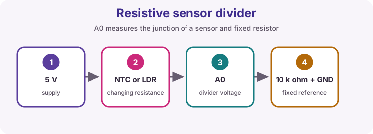
LDRs, thermistors and similar change resistance with light or temperature. Place the sensor in a divider with a fixed resistor; read the junction with analogRead. This course usually uses pull-up Rfixed to 5 V and the sensor to GND. Convert counts with calibration or a known model (Beta / Steinhart for NTC) - not guesswork.
Fixed resistor and sensor share the mid-point read by the ADC.
Tip: Same analogue ideas as the potentiometer lesson - the resistance just comes from the environment.
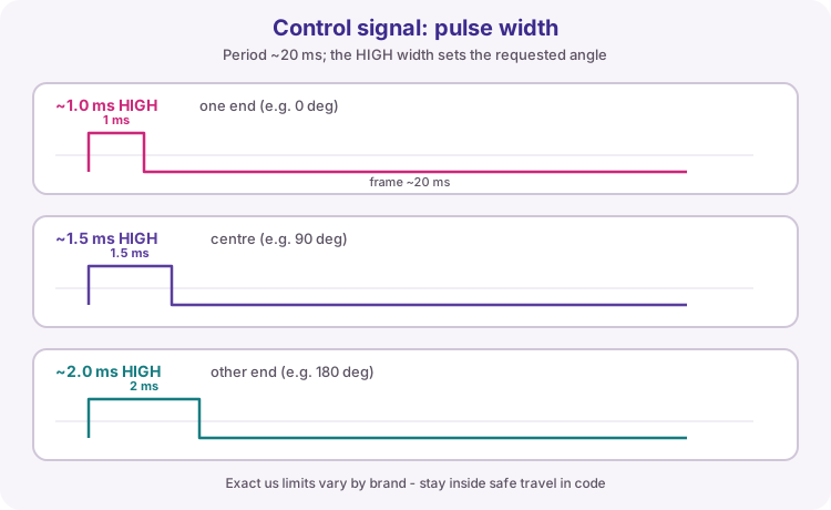
Hobby servos need periodic control pulses (about 1-2 ms width inside a ~20 ms frame) and adequate 5-6 V motor power with common GND to the Uno. Prefer the Servo library for angle control unless a lesson asks for hand-timed pulses.
If the board resets when the servo moves, the servo is starving the USB 5 V rail - use a separate 5 V supply.
Pulse width sets angle. Power the motor side properly.
Wire / need
Habit
Signal (usually yellow/orange)
Digital pin + Servo library
5 V / VIN motor power
Capable supply; not a weak USB-only setup if the servo stalls
GND
Common with the Uno
Brown-out / reset on move
Separate 5 V for the servo
Watch out: Do not power a stalling servo from the Uno 5 V pin alone on USB.
Pin map, conversions, common faults and glossary for oral checks and lab sheets. Keep this chapter open during assessments.
table
Uno pin map
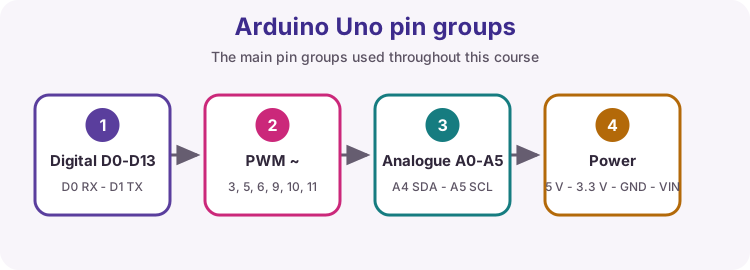
Classic Arduino Uno R3 roles used in this course (header layout matches R4 Minima for typical shields). Memorise PWM, I2C and UART pins - they appear in many labs.
Find power, digital, analogue and bus pins before you wire.
Group
Pins / notes
Digital I/O
D0-D13
Analogue in
A0-A5
PWM (~)
D3, D5, D6, D9, D10, D11
UART
D0 RX, D1 TX
I2C
A4 SDA, A5 SCL
SPI
D10-D13 (SS/MOSI/MISO/SCK)
External interrupts
D2, D3
Logic / current
5 V logic; R3 design ≤ 20 mA/I/O; R4 Minima ~8 mA/I/O
table
Units and conversions
Formulas students use constantly in labs. Keep units consistent (volts, ohms, amperes, milliseconds). Use a float operand when a division must keep a fraction.
Need
Formula / rule
ADC count to volts (default 5 V ref)
V = reading * 5.0 / 1023.0
Volts to ADC count (approx.)
reading ~= V * 1023.0 / 5.0
LED series resistor
R = (Vsupply - Vled) / Iled e.g. (5 - 2) / 0.010 = 300 ohm -> use 330 ohm
Ohms law
V = I * R
PWM duty (0-255)
About value/255 of the time HIGH; 0 = off, 255 = full on
millis interval
if (millis() - last >= intervalMs) { last = millis(); /* work */ }
Match the symptom to the usual cause before random rewiring. Many 'hardware' faults are = vs ==, floating inputs, baud mismatch or a buffer format error.
Symptom
Likely cause
What to check
Compile error near a later line
Missing ; on the previous line
Add the semicolon; read the first error, not only the last
Weird if behaviour / always true
Used = instead of ==
Comparisons need ==; = assigns
Pin never changes / floating input
Forgot pinMode or pull-up
pinMode in setup; buttons usually INPUT_PULLUP
Serial garbage or nothing
Baud mismatch or charge-only cable
Match Serial.begin and Monitor; use a data USB cable
LED dim/wrong or pin hot
No series resistor / overload
Add resistor; stay within ~20 mA per pin
Button flickers many times
Mechanical bounce
Debounce in software (Lesson 08)
Motor resets the board
Motor powered from Uno pin/USB alone
External motor supply + common GND + driver
Wrong average / truncated maths
Integer division
Use a float operand, e.g. total / 4.0
Crash or nonsense after many loops
int overflow or bad array index
Use long/unsigned long; stay inside array bounds
Garbage text from snprintf
Format code does not match argument type
Use %lu for unsigned long, %ld for long, dtostrf+%s for float
Terms you should be able to explain in assessment or oral checks. If a word appears in a lesson outcome, you should have a one-sentence definition ready.
ADC
Analogue-to-digital converter - turns a voltage into a count.
PWM
Pulse-width modulation - varies duty cycle of a digital pulse train.
UART
Asynchronous serial link (USB Serial on the Uno uses D0/D1).
GPIO
General-purpose input/output pin.
Pull-up
Resistor that holds an open input at a defined HIGH level.
Active-low
The active condition is logic LOW (common for INPUT_PULLUP buttons to GND).
Duty cycle
Fraction of time a PWM signal is HIGH.
Debounce
Ignoring extra edges from a bouncing mechanical switch so one press counts once.
Flyback diode
Diode across an inductive coil that safely absorbs turn-off voltage spikes.
C string
A char array ending in '\0' that print functions treat as text.
snprintf
Formats values into a char buffer with a size limit (safer than sprintf).
Format specifier
A % code in a format string (%d, %lu, %02d, %s) that consumes a matching argument.
dtostrf
Converts a float to a decimal char buffer - used on AVR when %f is unavailable.
Null terminator
The zero byte '\0' that marks the end of a C string.
ESP32 guide (Units G-I)
Lookup notes for the ESP32 track. Practical wiring and full sketches stay in lessons 34-50. Classic ESP32 DevKit / ESP32 Dev Module is the default lab board unless a lesson says otherwise.
note
ESP32 3.3 V I/O safety
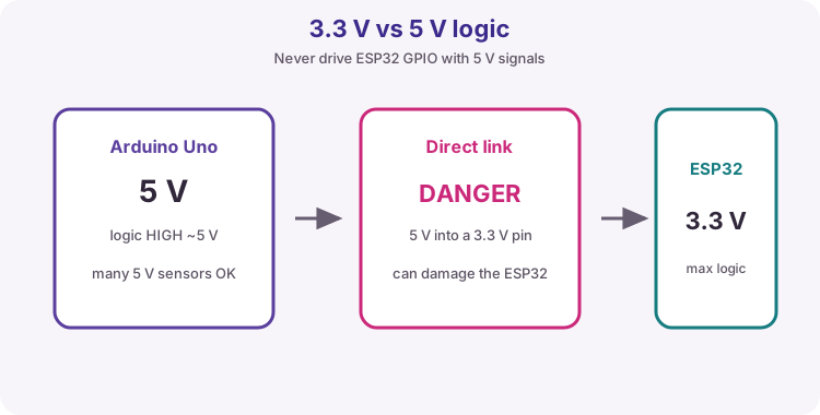
ESP32-family GPIO is 3.3 V class. Do not drive an ESP32 input from a 5 V Uno output or a 5 V sensor signal without level shifting. Many modules accept 5 V on USB or VIN while the chip I/O remains 3.3 V.
Design LED pin current around 12 mA or less. NeoPixel / WS2812 strips need an external 5 V supply and common GND for more than a few LEDs - do not power a long string from the ESP32 3.3 V pin.
Same IDE idea, different voltage class.table
Strapping pins and boot
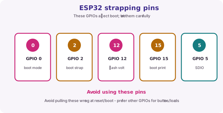
Some GPIOs are sampled at reset to select boot mode. Avoid using them for buttons that might be held during reset, or learn the safe idle level for your board. Exact sets vary by chip; classic ESP32 commonly cares about GPIO 0, 2, 12 and 15.
Check your module pinout before committing a wire.
Topic
Course habit
GPIO 0
Often BOOT - leave free or know pull state
GPIO 2
Often onboard LED - OK for blink; watch boot
GPIO 12 / 15
Strapping on classic ESP32 - prefer other pins for critical inputs
ADC1 pins
Prefer ADC1 (e.g. GPIO 34-39 on classic) when Wi-Fi is on
note
ESP32 ADC notes
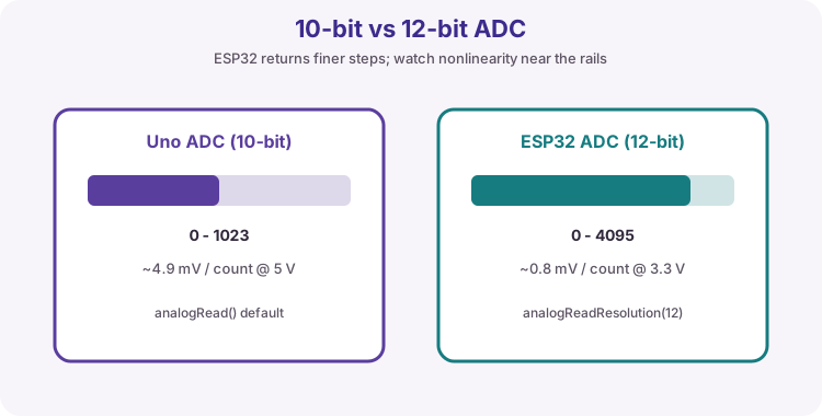
Arduino-ESP32 often exposes 12-bit analogRead (0-4095). That is not the same scale as Uno 0-1023. The ADC is useful for pots and relative sensing; it is not a precision lab meter. Attenuation settings change the usable voltage range. Nonlinearity is worse near the rails.
Classic ESP32 DAC exists on GPIO 25 and 26. Many C-series chips have no DAC - check the datasheet.
More counts, still not a calibrated instrument.note
WiFi Station and Access Point
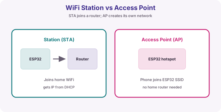
Station (STA): the ESP32 joins your router. After WL_CONNECTED, WiFi.localIP() is the LAN address (usually from DHCP); gatewayIP() is typically the router; RSSI() is signal strength in dBm (more negative is weaker).
Access Point (AP / SoftAP): the ESP32 creates a hotspot for phones to join (handy for first-time setup). softAPIP() is often 192.168.4.1 - a different address from the STA LAN IP.
Classic ESP32 is 2.4 GHz only. Use Serial.begin(115200). Keep WiFi credentials as placeholders - never commit real passwords to shared repos.
STA joins a router. AP is its own hotspot.table
HTTP request and response
HTTP is the text protocol behind browsers and many APIs. A request has a method and path; a response has a status code and often a body. Lesson 42 is HTTP server; lesson 43 is HTTP client.
Piece
Course habit
GET
Read a page or API document
POST
Send a body (form fields or JSON) to create/update
JSON (JavaScript Object Notation) is structured text used by almost every web API and many MQTT payloads. If you can read the braces and quotes, you can invent your own documents for a room node, weather reply or heater command.
ArduinoJson by Benoit Blanchon (JsonDocument in v7) turns that text into values your sketch can test. Workflow: HTTP status 200 (or a known MQTT string) -> deserializeJson -> check DeserializationError -> read fields with optional | defaults -> then act. Print the raw body when a path looks wrong.
The six JSON value types
"text"string
Always double quotes. Keys are strings too. Single quotes are invalid JSON.
21.5number
Integer or decimal. No units in the value - put units in the key name (temp_c).
true / falseboolean
Lowercase only. Not True or TRUE.
nullnull
Means no value. Different from 0 or "".
{ ... }object
Unordered set of "key": value pairs, comma-separated. Nested objects are normal.
[ ... ]array
Ordered list of values (any type). Index from 0.
Rules that break parsers
,Trailing comma
No comma after the last item in an object or array.
'Quotes
Keys and strings must use ". Comments (//) are not allowed in strict JSON.
NaNSpecial numbers
Avoid NaN / Infinity - many parsers reject them. Send null or omit the field.
UTF-8Encoding
Stick to plain UTF-8 text. Escape newlines inside strings as \n.
Path in the example
ArduinoJson read
Result type
room
doc["room"]
string
level
doc["level"] | 0
number (with default)
alert
doc["alert"] | false
boolean
sensor.temp_c
doc["sensor"]["temp_c"]
number (nested)
tags[0]
doc["tags"][0]
first array string
Tip: Course labs stay on plain HTTP JSON where possible so certificates do not hide the structure lesson.
Objects hold named fields. Arrays hold ordered items. Mix them freely: an object can contain an array of objects (weather forecasts, slide decks, RFID events).
Zero-based indexes: the first element is [0]. Missing keys or out-of-range indexes yield null / empty - use | defaults so your sketch does not act on garbage.
Write your own JSON
// Hand-built (small)String body = "{\"temp\":";
body += String(t, 1);
body += ",\"heater\":";
body += heaterOn ? "true" : "false";
body += "}";
// -> {"temp":21.5,"heater":false}// ArduinoJson build (safer for growth)
JsonDocument out;
out["temp"] = t;
out["heater"] = heaterOn;
serializeJson(out, Serial);
Design the document before the sketch. Pick short stable key names, one clear meaning each, and nest only when a group of fields belongs together (sensor, wifi, alarm).
Building text by hand is fine for small payloads: start with {, add "key": value pairs with commas, close with }. For larger documents, prefer ArduinoJson serializeJson so commas and quotes stay valid.
Tip: Match names exactly on publisher and subscriber - temp and Temp are different keys.
Parse checklist
1) Confirm the body is JSON (not an HTML error page). 2) deserializeJson into a JsonDocument. 3) If error, print the error and the raw body. 4) Read only the fields you need with | defaults. 5) Then drive GPIO / Serial / MQTT.
Mistake
Fix
Parse before HTTP 200
Check status first
Wrong nesting path
Print body; walk keys one level at a time
Expecting a number, got a string
API may send "21.5" - read as string or use as<float>() carefully
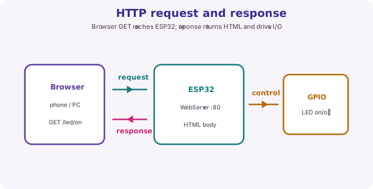
WebServer on port 80 maps URL paths to handler functions (server.on). loop must call server.handleClient() often - a long delay blocks the page.
A 303 redirect after an action (for example /led/on) sends the browser back to / so the page refreshes. Raw string literals R"=====( ... )=====" make HTML easier to embed without escaping every quote.
Request path selects the handler; response can be HTML or a redirect.table
MQTT, BLE and deep sleep
Quick map of Units H-I topics. Prefer the dedicated entries below for BLE, deep sleep, FreeRTOS and OTA. MQTT topics are exact string matches; payloads are often plain text or JSON.
Topic
One-line idea
MQTT
Publish/subscribe through a broker - live updates without HTTP polling
QoS / retain
Delivery effort and last-message memory on the broker (overview in lesson 44)
BLE
Phone talks to a GATT service/characteristic - prefer BLE over Classic SPP
Deep sleep
Timer or GPIO wake; RTC memory can keep a small counter
OTA
ArduinoOTA updates firmware over Wi-Fi after first USB upload
note
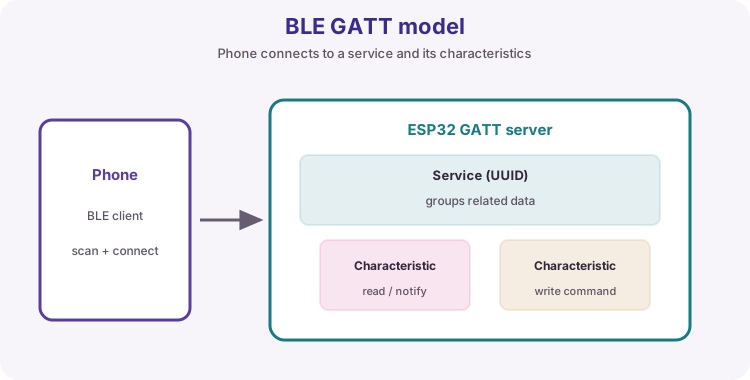
BLE GATT essentials
BLE peripheral advertises; phone (central) connects and uses GATT. A service groups characteristics; each characteristic is a readable/writable value identified by a UUID. Properties include READ, WRITE and NOTIFY. Labs often use custom 128-bit UUIDs.
Prefer BLE for short-range phone control without a router. Prefer Wi-Fi for LAN browsers, MQTT and cloud HTTP. Classic Bluetooth is legacy for new ESP32 labs. ESP32-P4 needs a companion radio for BLE.
Advertise, connect, write a characteristic, drive GPIO.
Term
Role
Peripheral / server
ESP32 advertising GATT
Central / client
Phone app
Service
Group of characteristics
Characteristic
The value you read or write
NOTIFY
Server pushes updates to the phone
note
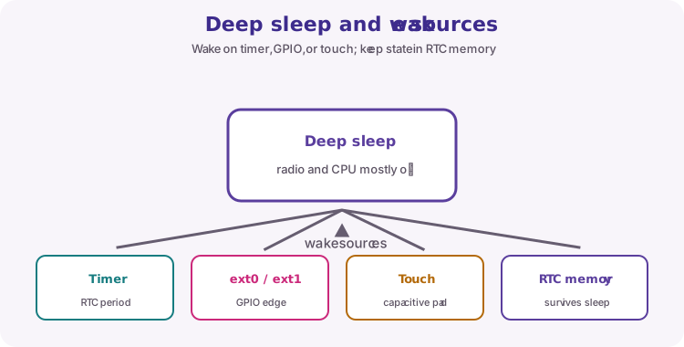
Deep sleep and wake
Deep sleep powers down most of the chip; normal SRAM is lost and wake typically restarts into setup(). Arm a timer with esp_sleep_enable_timer_wakeup(us) then call esp_deep_sleep_start(). Other wake sources include EXT0/EXT1 GPIOs and touch on supported pins.
RTC_DATA_ATTR keeps a variable across deep sleep but not across power loss - use Preferences/NVS for durable settings. DevKit USB-UART chips and LEDs can hide true sleep current on a USB meter.
Duty-cycle: wake, work, sleep.note
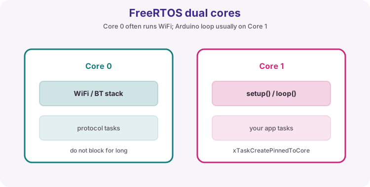
FreeRTOS tasks on ESP32
Arduino-ESP32 runs on FreeRTOS. setup()/loop() usually run on core 1; WiFi/BT work often uses core 0. Create workers with xTaskCreatePinnedToCore; wait with vTaskDelay(pdMS_TO_TICKS(ms)). Start stack sizes around 2048 and raise if the board reboots under load.
Shared globals without protection cause race conditions - use queues or mutexes when tasks share data. Do not add a task for every blink; millis in one loop is often enough.
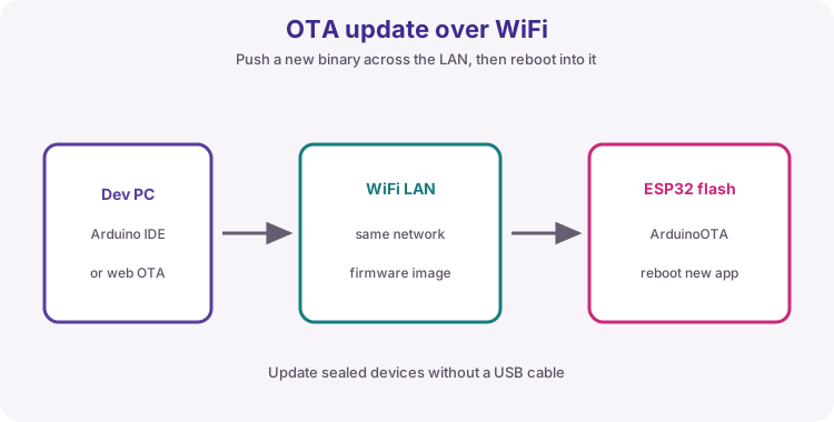
ArduinoOTA: after STA connect, call ArduinoOTA.begin() and ArduinoOTA.handle() often in loop. First flash is USB; later uploads can use Tools → Port → network hostname. Set a unique hostname and an OTA password outside trusted lab LANs. Keep USB recovery available.
HTTP OTA (device pulls an image URL) is the usual field-fleet pattern - different from IDE ArduinoOTA.
USB once, then network uploads with handle() kept alive.note
NeoPixel / WS2812 power
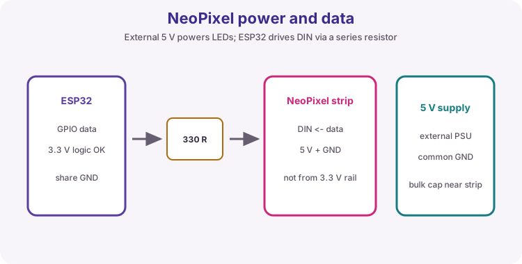
Addressable LEDs chain data (DIN to DOUT). Full white can draw about 60 mA per LED - budget the 5 V supply. Share GND with the ESP32. Put a series resistor on the data line (~330-470 ohm) and a bulk capacitor on 5 V near the strip. Call show() after you change pixel colours. Library for this course: Adafruit NeoPixel.
External 5 V for the strip; common GND; data from a GPIO.
Predict the Serial output before you upload. Then confirm in the Serial Monitor.
// Predict the Serial output before uploading.char line[24];
int values[] = {2, 4, 6, 8};
voidsetup() {
Serial.begin(9600);
int total = 0;
for (byte i = 0; i < 4; i++) {
total += values[i];
}
Serial.println(total); // 20
Serial.println(total / 4.0); // 5.00inthour = 9;
intminute = 5;
snprintf(line, sizeof(line), "%02d:%02d", hour, minute);
Serial.println(line); // 09:05unsignedlong t = 1234UL;
snprintf(line, sizeof(line), "t=%lu ms", t);
Serial.println(line); // t=1234 ms
}
voidloop() {}
Expected reasoning
The integer total is 20; 4.0 forces a floating-point average of 5.00.
%02d zero-pads hour and minute so 9:5 becomes 09:05.
%lu matches unsigned long - do not use %d for millis-scale values.
sizeof(line) tells snprintf the buffer limit so it cannot overrun.
Check your understanding
Q1. What runs once after reset, and what runs repeatedly?
Show answer
setup() runs once; loop() repeats.
Q2. What is the difference between = and ==?
Show answer
= assigns; == compares equality.
Q3. Why pass sizeof(buf) to snprintf?
Show answer
So the function knows the buffer limit and will not write past the end.
Q4. Which snprintf code should format unsigned long millis()?
Show answer
%lu
Q5. Why avoid %f with snprintf on a classic Uno?
Show answer
AVR float printf support is often disabled; use dtostrf into a char buffer then %s.
Q6. Why prefer millis over long delay calls in multi-task sketches?
Show answer
delay blocks loop; millis schedules work without stopping other tasks.
Q7. List the Uno PWM pins used with analogWrite.
Show answer
D3, D5, D6, D9, D10 and D11.
Q8. What is the recommended design current per Uno I/O pin?
Show answer
About 20 mA or less; 40 mA is an absolute maximum.
Extension challenge: Hand-write a one-page cheat sheet: Uno types with snprintf codes, INPUT_PULLUP truth, and the millis interval pattern. Answer oral questions without looking.