
11. PWM, millis() & State Machines
Explain PWM duty cycle with waveforms, drive brightness using analogWrite, and keep several tasks alive with millis and a simple state machine.
Learning outcomes
- Explain PWM as rapid digital switching with a duty cycle (not true analogue voltage)
- Use analogWrite on Uno PWM pins (~) with values 0-255
- Replace long delays with millis timing so loop can do more than one job
- Implement a simple state machine
Parts and preparation
Uno, LED, 330 ohm resistor and potentiometer.
Before power: inspect wiring, confirm supply voltage and ensure all connected circuits share GND.
What PWM is
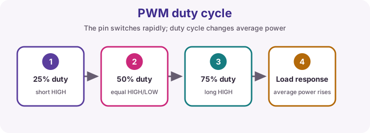
PWM means Pulse-Width Modulation. The pin still only drives LOW or HIGH (digital levels), but it switches many times per second. Duty cycle is the percentage of each period spent HIGH.
A larger duty cycle means more average power to a load such as an LED, so it looks brighter. A motor driver or MOSFET can use the same idea for average speed or power. PWM is not a true analogue mid-voltage from a DAC.
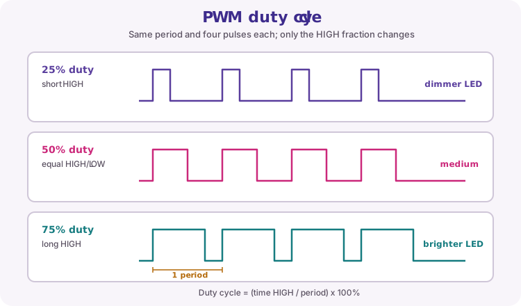
| Duty cycle | HIGH time share | Typical LED look |
|---|---|---|
| 0% | Always LOW | Off |
| 25% | Short HIGH | Dim |
| 50% | Half HIGH | Medium |
| 75% | Long HIGH | Bright |
| 100% | Always HIGH | Full on |
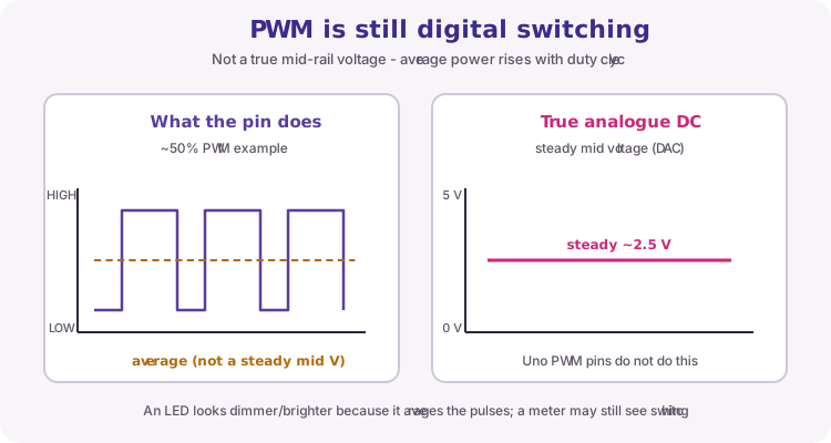
PWM is not true analogue
Lesson 10 used the ADC to measure many voltages. PWM goes the other way for control: it fakes a mid level by pulsing. An LED and your eye average the pulses. A slow multimeter may show a mid reading, but the pin is still switching HIGH/LOW.
Do not treat analogWrite as producing a clean DC voltage for precision analogue circuits. Use it for brightness, simple motor enable/PWM speed, and similar average-power jobs.
analogWrite on the Uno
analogWrite(pin, value) sets the PWM duty on pins marked ~ : 3, 5, 6, 9, 10 and 11. value is 0-255 (8-bit). 0 is off, 255 is full on, mid values set the duty cycle.
Call pinMode(pin, OUTPUT) first. Heavy loads still need a driver (lesson 12) - PWM only controls the pin; it does not raise the pin current limit.
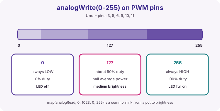
const byte ledPin = 9;  // must be a ~ PWM pin

pinMode(ledPin, OUTPUT);
analogWrite(ledPin, 0);    // off
analogWrite(ledPin, 127);  // about half
analogWrite(ledPin, 255);  // full
Non-blocking time with millis
delay() stops the whole sketch until the wait finishes, so other work cannot run. millis() returns milliseconds since the board started (unsigned long). Save a timestamp and compare: if enough time has passed, do the task and update the timestamp. loop() can then keep reading sensors and updating PWM while reports run on a slower schedule.
unsigned long lastReport = 0;

if (millis() - lastReport >= 500) {
  lastReport = millis();
  // do the slow task here (e.g. Serial.println)
}
State machine idea
A state variable records the current phase of a behaviour (for example IDLE, ON, WAIT). Events and timers decide when to move to another state. Combined with millis, you can run timed sequences without long delay() calls blocking the rest of the sketch.
Wiring and safe build sequence
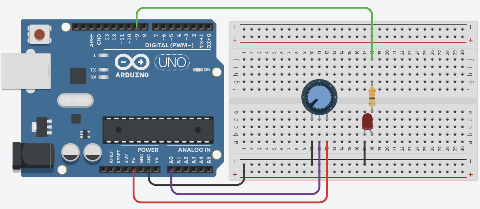
- D9 -> 330 ohm -> LED anode
- LED cathode -> GND
- Potentiometer wiper -> A0; outer legs -> 5 V and GND
Worked sketch
Download .ino sketchconst byte ledPin = 9;
unsigned long lastReport = 0;
void setup() {
pinMode(ledPin, OUTPUT);
Serial.begin(9600);
}
void loop() {
int raw = analogRead(A0);
byte brightness = map(raw, 0, 1023, 0, 255);
analogWrite(ledPin, brightness);
if (millis() - lastReport >= 500) {
lastReport = millis();
Serial.println(brightness);
}
}How the code works
- D9 is a PWM (~) pin so analogWrite can set duty cycle.
- map converts the ADC reading (0-1023) into a PWM value (0-255).
- LED response stays immediate because no delay blocks loop.
- The Serial report task runs only every 500 ms via millis.
Test and record evidence
Practical evidence checklist
Common faults and checks
- Use a pin marked ~ for PWM (3, 5, 6, 9, 10, 11 on Uno).
- Do not connect a motor in place of the LED without a driver and flyback protection.
- If brightness never changes, check pot wiring to A0 and that ledPin is a PWM pin.
Check your understanding
Q1. Is PWM a true analogue output?
Show answer
No; it is a digital pulse train with variable duty cycle.
Q2. What does duty cycle mean?
Show answer
The percentage of each PWM period that the pin is HIGH.
Q3. What range does analogWrite use on the Uno?
Show answer
0 to 255.
Q4. Why prefer millis for multi-task programs?
Show answer
It schedules work without stopping the rest of loop.