
01. Safety, Electricity & Breadboards
Work safely with ELV DC, use Ohms law for LED resistors, and read a breadboard correctly.
Learning outcomes
- Explain voltage, current and resistance and state Ohms law
- Calculate and choose a safe series resistor for an LED
- Describe breadboard terminal rows and power rails (including mid-rail splits)
- Use a multimeter for voltage, and avoid dangerous current/resistance mistakes
- Build and test a blinking LED on D8 with common GND
Parts and preparation
Arduino Uno, USB data cable, breadboard, red LED, 220-330 ohm resistor, jumper wires and a digital multimeter.
Before power: inspect wiring, confirm supply voltage and ensure all connected circuits share GND.
Why this lesson comes first
Before programming, you need safe habits and a working first circuit. This lesson introduces the three electrical quantities you will use constantly, shows how to protect an LED and an Uno pin with a resistor, and explains how a breadboard connects holes.
Voltage, current and resistance
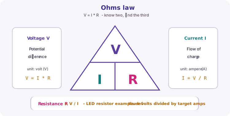
Voltage (V) is electrical potential difference - how hard the supply pushes. Current (I) is the flow of charge. Resistance (R) opposes that flow.
Ohms law links them: V = I * R. Rearrange as I = V / R or R = V / I when you know two values.
| Quantity | Symbol | Unit |
|---|---|---|
| Voltage | V | volt (V) |
| Current | I | ampere (A) - often mA in labs |
| Resistance | R | ohm |
Choosing an LED series resistor
An LED needs a series resistor so current stays within safe limits for the LED and the Uno pin (design around 20 mA or less per pin on classic Uno R3).
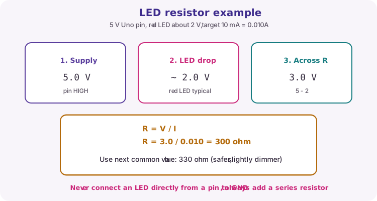
Course example: 5 V pin, red LED drop about 2 V, target 10 mA (0.010 A). Voltage across the resistor is 5 - 2 = 3 V. R = 3 / 0.010 = 300 ohm. Use the next common value 330 ohm - slightly safer and a little dimmer.
Never connect an LED directly from a pin to GND.
// Target ~10 mA with ~2 V LED on a 5 V pin
// R = (5.0 - 2.0) / 0.010 = 300 ohm -> use 330 ohm
LED polarity and course wiring
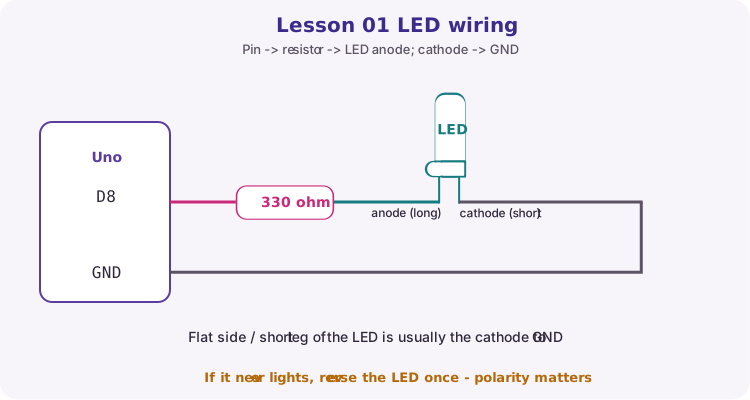
LEDs only conduct usefully in one direction. The long leg is usually the anode; the short leg / flat side is usually the cathode.
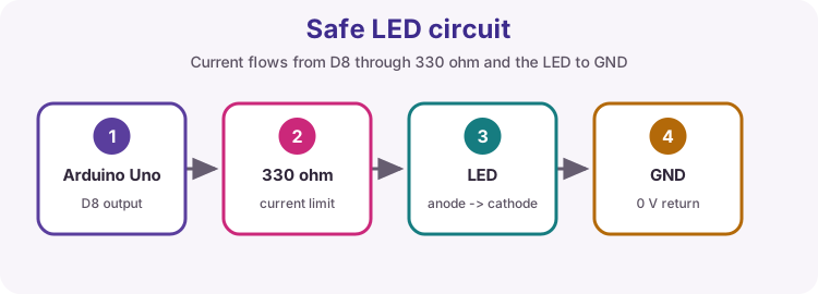
Course wiring for this lesson: D8 -> 330 ohm -> LED anode; LED cathode -> GND.
Breadboard connections
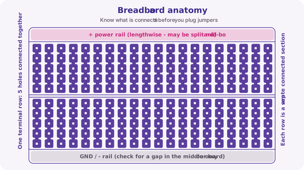
On a typical solderless breadboard, the five holes in one terminal strip letter-row group are connected. The next letter row is a different connection - that is how you place a resistor so each end is in a different node.
Long side rails distribute power lengthwise. Many boards split those rails in the middle - use continuity mode to check before you assume + or GND runs the full length.
Multimeter without drama
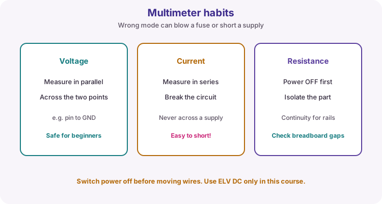
Voltage: measure in parallel across two points (for example D8 to GND while HIGH). Current: measure in series - you must break the circuit; never put the meter across a supply on current mode. Resistance / continuity: power off first; useful for checking breadboard rails and dead jumpers.
Safety rules for this course
Use only extra-low-voltage DC. Switch power off before rewiring. Never measure resistance on a powered circuit. When measuring current, place the meter in series - never directly across a supply.
Keep fingers and metal tools clear of shorting adjacent header pins while powered.
| Do | Do not |
|---|---|
| Power off before moving wires | Rewire live circuits |
| Share GND with the Uno | Float sensor grounds |
| Use a series resistor with LEDs | Connect LED pin-to-GND bare |
| ELV DC only | Connect mains electricity |
Wiring and safe build sequence
- Uno D8 -> 330 ohm resistor (one end)
- Other resistor end -> LED anode (long leg)
- LED cathode (flat / short leg) -> GND
- Confirm resistor and LED share connected breadboard rows correctly (different nodes for each lead)
Worked sketch
Download .ino sketchconst byte ledPin = 8;
void setup() {
pinMode(ledPin, OUTPUT);
}
void loop() {
digitalWrite(ledPin, HIGH);
delay(500);
digitalWrite(ledPin, LOW);
delay(500);
}How the code works
- pinMode configures pin 8 as an OUTPUT before you drive it.
- HIGH is about 5 V on an Uno; LOW is about 0 V.
- The resistor limits LED and pin current - it is not optional.
- delay(500) makes a clear blink for this first build; later lessons replace long delays when many tasks must run.
Test and record evidence
Practical evidence checklist
Common faults and checks
- Reverse the LED if it never lights (polarity).
- Confirm the resistor and LED meet in a connected breadboard node, and return to a real Uno GND.
- Dim or dead: try a known-good LED and check for a mid-rail power split.
- Board not responding: use a USB data cable and select board/port (Lesson 03).
Check your understanding
Q1. State Ohms law.
Show answer
V = I * R (voltage equals current times resistance).
Q2. Why does an LED need a series resistor?
Show answer
To limit current through the LED and the Arduino pin.
Q3. How are breadboard terminal holes usually connected?
Show answer
In groups of five along a strip; power rails run lengthwise and may be split.
Q4. How should you measure voltage with a meter?
Show answer
In parallel across the two points of interest.
Q5. Why is current mode across a supply dangerous?
Show answer
The meter is nearly a short - it can blow a fuse or stress the supply.