
31. College Practical Assessments
Complete three practical tasks and a code-correction exercise with planning, safe build, measured evidence and printable rubrics.
Learning outcomes
- Interpret a practical brief into IPO, pin and power plans before wiring
- Complete Task A two-button controller with debounce, three states and Serial reports
- Complete Task B sensor alarm with calibration, hysteresis and safe alarm drive
- Complete Task C integrated system with I2C display, dual sensing and non-blocking timing
- Diagnose and repair common sketch defects and explain each fix
- Submit portfolio evidence against the rubric for each assessment
Parts and preparation
Uno starter kit (buttons, LEDs, resistors, analogue sensor, I2C LCD or equivalent, actuator/buzzer as required by each task), multimeter, breadboard, jumpers, practical logbook, and the printable rubrics from this lesson.
Before power: inspect wiring, confirm supply voltage and ensure all connected circuits share GND.
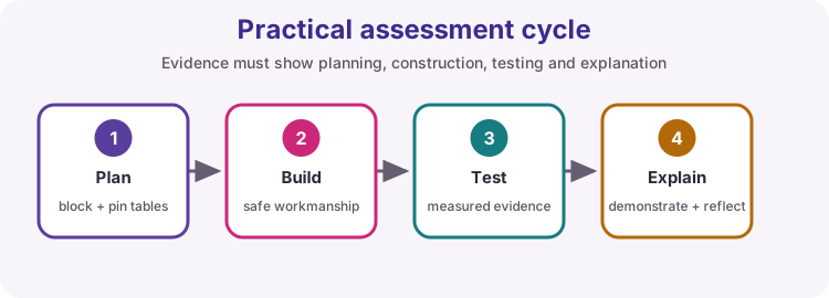
How assessment works on this course
Each practical is marked with its own criteria grid. Open the rubric before you start so you know what evidence is required. Use Print / Save as PDF from the rubric page if you need a paper copy.
Workflow for every task: read the brief; list success criteria; draw IPO / block diagram; prepare a pin table and power note; build and test modules; integrate; fill the test table; submit portfolio items listed on the rubric.
| Assessment | Focus | Rubric file |
|---|---|---|
| Task A | Two-button controller | rubric-task-a-two-button.html |
| Task B | Sensor alarm + hysteresis | rubric-task-b-sensor-alarm.html |
| Task C | Integrated system | rubric-task-c-integrated.html |
| Code correction | Find and fix sketch faults | rubric-code-correction.html |
Evidence every assessor expects
Software that 'mostly works' is not enough. Across Tasks A-C you should be able to show:
1. Planning artefacts produced before energising 2. Safe wiring (series resistors, common GND, drivers for heavy loads) 3. A test table: condition, expected, measured/observed, pass/fail 4. At least one fault found and how you fixed it 5. A short explanation of decisions (oral or written)
Use Lesson 25 fault-finding habits: measure, do not randomly rewire.
| Artefact | Why it is marked |
|---|---|
| Block / IPO diagram | Shows you understood the brief |
| Pin and power plan | Prevents conflicts and brown-outs |
| Test table | Proves criteria, not anecdotes |
| Fault log | Shows diagnostic skill |
| Rubric scoresheet | Assessor records marks and notes |
Practical Task A - Two-button controller
Brief: two debounced buttons select three distinct LED/PWM output states. Serial reports each state change. Submit a truth table that matches the demo.
Suggested course pins: button A on D2 to GND (INPUT_PULLUP), button B on D3 to GND, status LED on D5, PWM LED on D6. Name your own pins in the pin table if the brief differs.
Marking emphasises debounce quality, agreement between truth table and behaviour, and clean Serial messages (no flood while a button is held).
| Must demonstrate | Typical evidence |
|---|---|
| Debounce both buttons | No chatter on Serial |
| Three distinct states | Truth table + live demo |
| Serial on change only | Screenshot or log excerpt |
| Safe LED wiring | Series resistors shown |
Practical Task B - Sensor alarm
Brief: read one analogue sensor, display a calibrated engineering value, and drive an alarm through safe hardware. Use hysteresis (separate on and off thresholds) so the alarm does not chatter.
Choose a sensor you already practised (potentiometer, LDR, thermistor, etc.). Document the conversion formula or calibration points before the final demo. If the alarm load needs more current than a pin can supply, use a driver (lesson 12).
| Must demonstrate | Typical evidence |
|---|---|
| Calibrated display | Formula + Serial/LCD reading |
| Hysteresis | On/off thresholds written and shown |
| Three conditions | Below / near / above in test table |
| Safe alarm path | Driver/diode/GND as required |
Practical Task C - Integrated system
Brief: combine an I2C display, one digital input/sensor, one analogue sensor and one actuator. Keep the system responsive with non-blocking timing (millis).
Prove each subsystem alone, then merge. Watch pin conflicts: I2C uses A4/A5 on the Uno. Success criteria must be written before the end-to-end demo; the rubric checks that you met every criterion.
| Subsystem | Acceptance check |
|---|---|
| I2C display | Shows live useful text; address documented |
| Digital channel | Reliable read; logic documented |
| Analogue channel | Reading changes with stimulus |
| Actuator | Safe drive; responds to logic |
| Timing | No long delay freezing the UI |
Code-correction exercise
You are given a faulty sketch (use the downloadable faulty starter below, or a lecturer variant). Find and repair every defect, then explain these classes:
- Capitalisation / identifiers (pinMode vs PinMode, Serial vs serial) - Pin modes that match the wiring - Comparison == versus assignment = - Matching braces - Required semicolons
Attempt the repair before opening the fixed reference sketch on this page. The rubric marks your inventory and explanation, not only a compiling file.
// FAULTY STARTER - repair before comparing to the fixed reference.
byte InputPin = 2;
byte outputPin = 13;

void setup() {
  PinMode(InputPin, INPUT);
  pinMode(outputPin, OUTPUT)
  Serial.begin(9600);
}

void loop() {
  if (digitalRead(InputPin) = LOW) {
    digitalWrite(outputPin, HIGH);
  else {
    digitalWrite(outputPin, LOW);
  }
}
How the criteria grid is marked
Each rubric is a full matrix for that assessment. Rows cover planning, code, hardware, diagram, I/O, BOM/safety, testing, resolved challenges, unresolved challenges and explanation as needed for the brief.
Four levels on every row (tick or circle one cell only): - Excellent - Proficient - Basic - Poor
There is no separate score column. Always use the rubric grid for the assessment you are sitting.
Wiring and safe build sequence
- Before any task: labelled connection diagram, pin table and power note submitted or shown to the assessor
- Common GND across Uno, modules and any external supply
- Series resistors on LEDs; INPUT_PULLUP buttons to GND unless the brief specifies otherwise
- Drivers and flyback protection for relays, motors, solenoids or heavy buzzers
- Instructor or peer short-check before first power-up
Code correction - fixed reference
Download .ino sketch// Code-correction FIXED REFERENCE
// Use only after attempting the faulty starter (31-code-faults.ino).
const byte inputPin = 2;
const byte outputPin = 13;
void setup() {
pinMode(inputPin, INPUT_PULLUP); // button to GND
pinMode(outputPin, OUTPUT);
Serial.begin(9600);
}
void loop() {
bool pressed = digitalRead(inputPin) == LOW; // compare, do not assign
if (pressed) {
digitalWrite(outputPin, HIGH);
} else {
digitalWrite(outputPin, LOW);
}
}How the code works
- This file is the corrected reference for the code-correction exercise.
- Faulty starter: 31-code-faults.ino (PinMode, missing semicolon, = instead of ==, missing brace, wrong pin mode).
- Learners must explain capitalisation, pin modes, comparison, braces and semicolons on the rubric.
- Download and print the matching rubric HTML for Tasks A, B, C and code correction before the practical.
Faulty starter for code correction
Download .ino sketchWhat this sketch is for: Deliberately broken sketch for the code-correction assessment. Repair it, then compare with the fixed reference above.
// FAULTY STARTER - repair before comparing to the fixed reference.
byte InputPin = 2;
byte outputPin = 13;

void setup() {
  PinMode(InputPin, INPUT);
  pinMode(outputPin, OUTPUT)
  Serial.begin(9600);
}

void loop() {
  if (digitalRead(InputPin) = LOW) {
    digitalWrite(outputPin, HIGH);
  else {
    digitalWrite(outputPin, LOW);
  }
}
How the code works
- PinMode should be pinMode (capitalisation).
- Button circuit needs INPUT_PULLUP when wired to GND.
- Missing semicolon after pinMode(outputPin, OUTPUT).
- if condition must use == not =.
- Missing closing brace before else.
Test and record evidence
Practical evidence checklist
Common faults and checks
- Return to the block diagram and test one subsystem when integration fails.
- Use compiler messages and measured voltages rather than random rewiring.
- If Serial floods, print only on state change and verify debounce.
- If an alarm chatters, implement separate on/off thresholds (hysteresis).
- If the display is blank on Task C, run an I2C scanner and confirm address/wiring.
Check your understanding
Q1. What should be produced before wiring?
Show answer
A block diagram, pin plan, power plan and connection diagram.
Q2. What demonstrates testing?
Show answer
A table of conditions, expected values, measured/observed values and pass/fail results.
Q3. Why does Task B require hysteresis?
Show answer
So the alarm does not chatter when the reading sits near a single threshold.
Q4. Why attempt the faulty sketch before the fixed reference?
Show answer
The rubric marks your fault inventory and explanation, not only a working paste.
Q5. Which Uno pins does I2C use that Task C must keep free of conflicts?
Show answer
A4 (SDA) and A5 (SCL).