
26. Capstone 1: Environmental Monitor
Integrate DHT11, LDR, I2C LCD and a temperature alarm into one monitored system.
Learning outcomes
- Draw input-process-output blocks for sensors, validation, display and alarm
- Wire DHT11, LDR divider and I2C LCD on non-conflicting pins
- Sample with millis every two seconds without blocking delay
- Reject failed DHT readings with isnan and keep the alarm silent
- Calibrate and document a temperature alarm threshold with a test table
Parts and preparation
Uno, DHT11 (bare with 4.7-10 k ohm pull-up, or 3-pin module), LDR with series resistor for a voltage divider, I2C 1602 LCD (backpack), passive buzzer, jumpers. Install the same libraries as lessons 17 and 18.
Before power: inspect wiring, confirm supply voltage and ensure all connected circuits share GND.
Libraries for this lesson
In Arduino IDE 2 open Tools → Manage Libraries…. Search by the Library Manager name and install the package by the exact author below. Similar names from other authors can use different APIs and will break the example.
| Include | Library Manager name | Author | Install note |
|---|---|---|---|
Wire.h | Wire | Arduino | Built into the Arduino core. No Library Manager install required. |
LiquidCrystal_I2C.h | LiquidCrystal I2C | Frank de Brabander | Same package as lesson 17. Install via Library Manager. |
DHT.h | DHT sensor library | Adafruit | Same package as lesson 18. Install via Library Manager. |
(dependency) | Adafruit Unified Sensor | Adafruit | Required with the DHT sensor library. |
Design before you solder
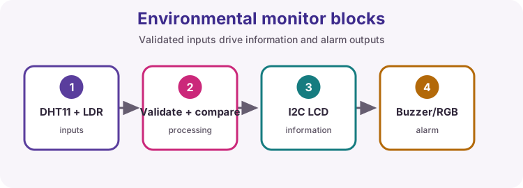
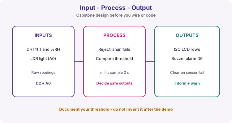
This capstone combines lessons you already passed: DHT (18), LDR divider (20) and I2C LCD (17). Start on paper with Input-Process-Output so every wire and if-statement has a job.
Inputs are temperature, humidity and light. Processing validates readings and compares a threshold. Outputs are LCD information and an audible warning.
Course pin map
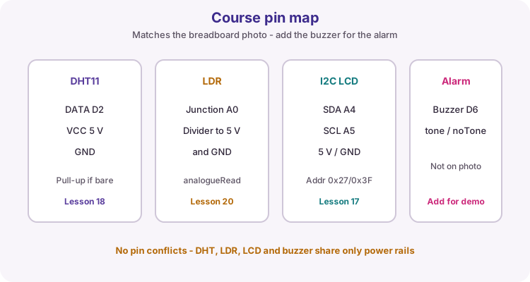
The breadboard photo under Wiring matches the sensing and display half of the build. DHT DATA on D2, LDR junction on A0, LCD on the Uno I2C pins (A4/SDA and A5/SCL, or the dedicated SDA/SCL headers).
Add a passive buzzer on D6 for the alarm. That part is in the worked sketch but not on the photo.
| Function | Uno pin |
|---|---|
| DHT DATA | D2 |
| LDR divider junction | A0 |
| I2C LCD SDA / SCL | A4 / A5 (or SDA / SCL headers) |
| Passive buzzer | D6 |
| Module power | 5 V and GND rails |
Integrate one subsystem at a time
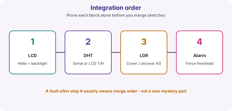
Do not upload the full sketch on day one. Prove LCD Hello World, then DHT on Serial or LCD, then LDR cover/uncover on A0, then force the alarm with a temporary low threshold.
Combine only after each block passes its own check. A fault after the merge usually means merge order - not a new mystery component.
Sample with millis, not delay
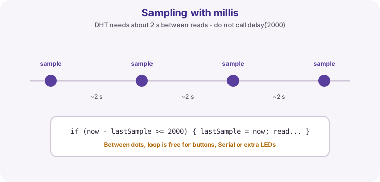
DHT sensors need about two seconds between reads. Using delay(2000) freezes the whole sketch. Use millis so loop stays free for Serial, buttons or extra LEDs later.
Pattern: if (now - lastSample >= 2000) { lastSample = now; read and update; }
LCD layout and clean rows
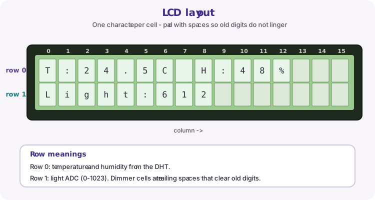
Row 0 shows temperature and humidity. Row 1 shows the light ADC value (0-1023 on the Uno). Print trailing spaces so shorter numbers do not leave old digits on the glass.
If your backpack address is 0x3F instead of 0x27, change the LiquidCrystal_I2C constructor (lesson 17 scanner).
Validate before you alarm
dht.readTemperature() and readHumidity() return NAN on a failed transfer. Check isnan(t) || isnan(h) before comparing thresholds. On failure show Sensor error, call noTone, and do not treat the last good temperature as still valid.
Course default alarm: t >= 30.0 C. Warm the sensor gently or lower the constant for a demo, then restore and document the value you assess against.
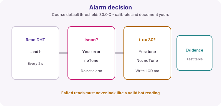
| Condition | LCD | Buzzer |
|---|---|---|
| isnan(t) or isnan(h) | Sensor error | Off |
| Valid and t < threshold | T / H / Light | Off |
| Valid and t >= threshold | T / H / Light | On (tone) |
Assessment evidence
College practicals mark process as well as a working board. Prepare:
1. IPO / block diagram 2. Wiring diagram or annotated breadboard photo 3. Commented sketch with named pins and threshold constant 4. Test table at three conditions (cool, near threshold, hot or forced) 5. One fault you found and how you fixed it 6. Short demo checklist (LCD update, light change, alarm on/off, sensor unplug error)
Wiring and safe build sequence
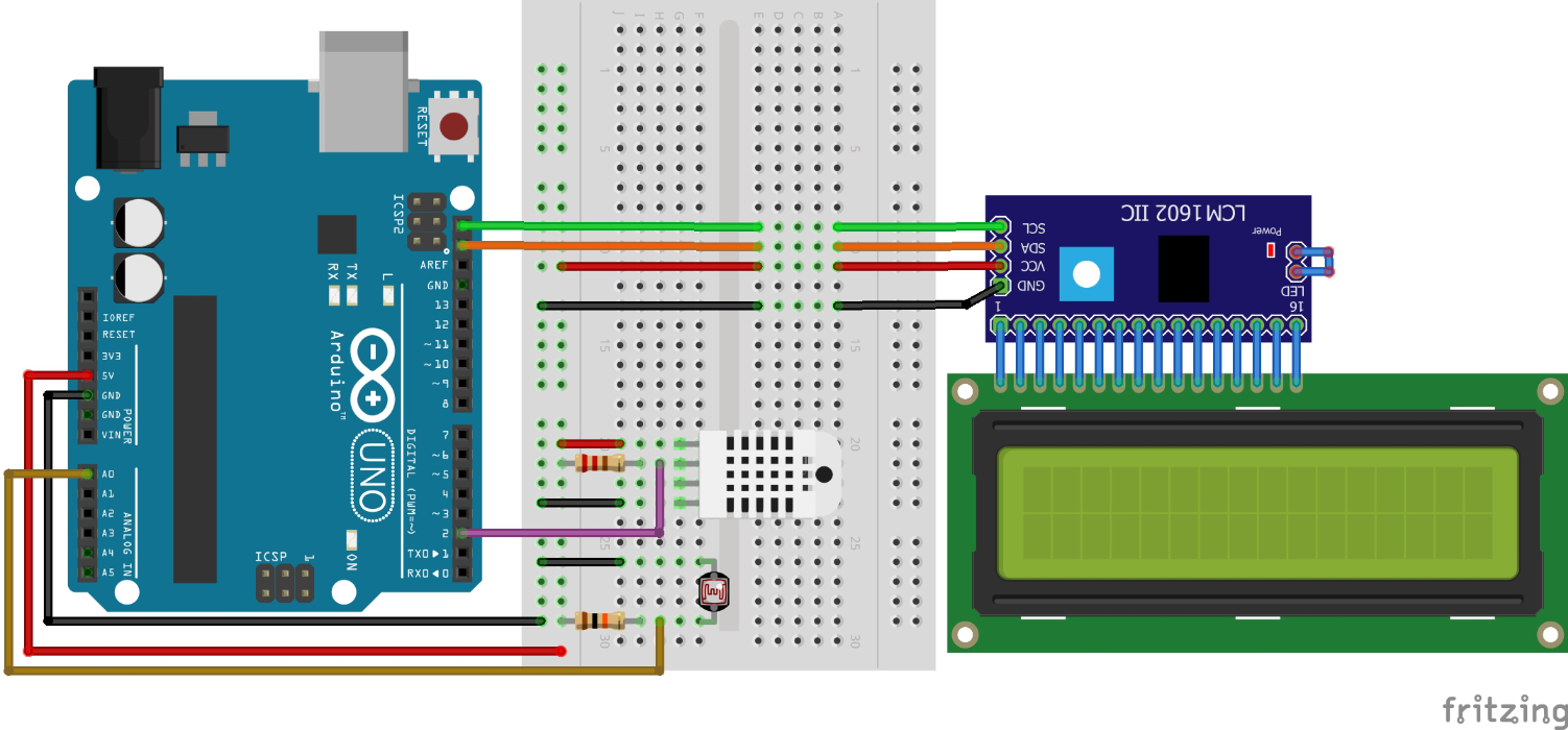
- 5 V and GND to the breadboard rails; all modules share GND
- DHT DATA -> D2 (pull-up DATA to 5 V if using a bare sensor)
- DHT VCC -> 5 V, DHT GND -> GND
- LDR divider: one side to 5 V, other side through resistor to GND; junction -> A0
- I2C LCD VCC/GND -> 5 V/GND; SDA -> A4 (or SDA); SCL -> A5 (or SCL)
- Passive buzzer signal -> D6 (add this for the alarm if not on the breadboard photo)
Worked sketch
Download .ino sketch#include <Wire.h>
#include <LiquidCrystal_I2C.h>
#include <DHT.h>
const byte dhtPin = 2;
const byte buzzerPin = 6;
const byte lightPin = A0;
const float alarmCelsius = 30.0; // Document the value you calibrate to
LiquidCrystal_I2C lcd(0x27, 16, 2); // Try 0x3F if the display stays blank
DHT dht(dhtPin, DHT11);
// DHT dht(dhtPin, DHT22); // Use this instead if you fitted a DHT22
unsigned long lastSample = 0;
const unsigned long sampleMs = 2000;
void setup() {
pinMode(buzzerPin, OUTPUT);
noTone(buzzerPin);
Serial.begin(9600);
lcd.init();
lcd.backlight();
dht.begin();
lcd.clear();
lcd.print("Env monitor");
lcd.setCursor(0, 1);
lcd.print("Sampling...");
Serial.println("Environmental monitor ready");
}
void loop() {
unsigned long now = millis();
if (now - lastSample < sampleMs) {
return;
}
lastSample = now;
float t = dht.readTemperature();
float h = dht.readHumidity();
int light = analogRead(lightPin);
if (isnan(t) || isnan(h)) {
lcd.setCursor(0, 0);
lcd.print("Sensor error ");
lcd.setCursor(0, 1);
lcd.print("Check DHT wiring");
noTone(buzzerPin);
Serial.println("DHT read failed");
return;
}
lcd.setCursor(0, 0);
lcd.print("T:");
lcd.print(t, 1);
lcd.print("C H:");
lcd.print(h, 0);
lcd.print("% ");
lcd.setCursor(0, 1);
lcd.print("Light:");
lcd.print(light);
lcd.print(" ");
if (t >= alarmCelsius) {
tone(buzzerPin, 1000);
} else {
noTone(buzzerPin);
}
Serial.print("T=");
Serial.print(t, 1);
Serial.print(" H=");
Serial.print(h, 0);
Serial.print(" Light=");
Serial.println(light);
}How the code works
- Named pins and alarmCelsius make the assessment sketch easy to mark and retune.
- isnan failure shows a clear LCD message and forces the buzzer off.
- Trailing spaces on both rows clear leftover digits when values get shorter.
- Change 0x27 to 0x3F (or your scanner result) if the LCD stays blank.
Test and record evidence
Practical evidence checklist
Common faults and checks
- Blank LCD: run the lesson 17 I2C scanner; try address 0x3F; check SDA/SCL and backlight jumper.
- Sensor error always: confirm DHT DATA on D2, 5 V, GND, and pull-up on bare sensors.
- Light stuck: check the divider to 5 V and GND and that A0 is on the junction.
- No beep when hot: confirm passive buzzer on D6, or lower alarmCelsius briefly for a bench test.
- Everything wrong after a big merge: retest LCD, DHT, LDR and alarm as separate sketches.
Check your understanding
Q1. Why integrate one subsystem at a time?
Show answer
It localises faults and confirms each interface independently.
Q2. Why use millis instead of delay(2000) for DHT sampling?
Show answer
delay freezes the whole sketch; millis lets other work keep running between samples.
Q3. What must happen on an isnan DHT failure?
Show answer
Show a clear error, silence the buzzer, and do not treat the reading as a valid temperature.
Q4. What evidence proves calibration?
Show answer
Recorded conditions, readings, chosen threshold and the observed alarm output.