
29. Interrupts on the Uno
Catch a button press the moment it happens with an interrupt on D2, keep the interrupt function tiny with a volatile flag, and do the real work in loop(). An optional appendix covers the Uno's other interrupt sources and sleep.
Learning outcomes
- Explain the difference between checking a pin with digitalRead (polling) and being told by an interrupt
- Use attachInterrupt on D2 or D3 with digitalPinToInterrupt and the right trigger mode
- Follow the three ISR rules: keep it tiny, mark shared variables volatile, copy bigger numbers safely
- Use the flag pattern: the ISR raises a flag, loop() lowers it and does the work
- Explain why one press can count more than once (bounce) and how to ignore the extra edges
- Optional appendix: recognise the pin-change, timer, USART, ADC, comparator and watchdog interrupt templates
- Optional appendix: put the Uno into power-down sleep and wake it with an interrupt
Parts and preparation
Uno, push-button, LED with a 330 ohm resistor, passive buzzer, breadboard and jumper wires. Serial Monitor at 9600 baud.
Before power: inspect wiring, confirm supply voltage and ensure all connected circuits share GND.
What an interrupt does
So far your sketches have checked things for themselves: loop() runs digitalRead, looks at the answer and moves on. That is called polling.
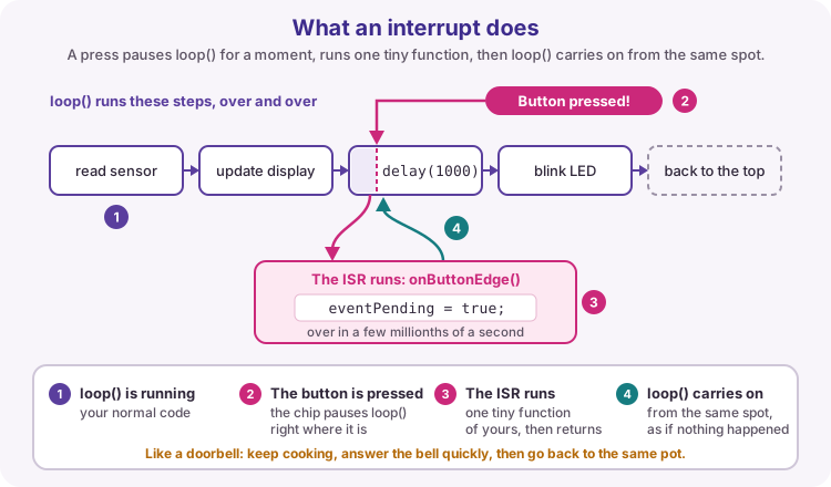
An interrupt works the other way round. The chip's hardware watches a pin for you. When the event you asked for happens - say, the button on D2 is pressed - the chip pauses loop() right where it is, runs one small function of yours, then carries on from exactly the same spot. That small function is called an ISR, short for interrupt service routine.
Think of a doorbell. You get on with cooking and don't keep walking to the door to check. When the bell rings, you answer it quickly, then go back to the pot you were stirring.
Why not just use digitalRead?
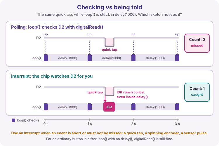
digitalRead only sees the button at the moment that line runs. If loop() is busy - a delay(1000), a slow display update, a long calculation - a quick tap can start and finish between two checks, and the sketch never knows it happened.
An interrupt can't miss it like that, because the hardware watches the pin all the time, even during delay(). You will see this for yourself in the Step 1 test sketch below.
Use an interrupt when an event is short or must not be missed: a quick tap, the pulses from a spinning knob (an encoder), or a sensor that sends a brief pulse. For an ordinary button in a fast loop() with no delay(), the digitalRead method from Lesson 10 is still fine.
D2 and D3: the interrupt pins
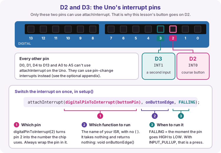
On the Uno only two pins can use attachInterrupt: D2 (its hardware name is INT0) and D3 (INT1). That is why the button for this lesson goes on D2. Other pins can use a different kind, pin-change interrupts, which are in the optional appendix.
You switch the interrupt on once, in setup(), with attachInterrupt. It needs three things: which pin, which function to run, and when to run it. Always wrap the pin number in digitalPinToInterrupt() - it turns pin 2 into the number the chip uses, so you never have to remember it.
Here is the smallest working example. Wire a button from D2 to GND, upload it, open Serial Monitor at 9600 baud and press the button. You should see Pressed! for each press - sometimes twice, which is bounce, explained further down.
const byte buttonPin = 2;          // D2 = interrupt pin INT0

volatile bool eventPending = false;  // volatile: see the rules below

// The ISR: runs by itself when the button is pressed
void onButtonEdge() {
  eventPending = true;               // just raise the flag
}

void setup() {
  pinMode(buttonPin, INPUT_PULLUP);  // pressed reads LOW
  Serial.begin(9600);
  attachInterrupt(digitalPinToInterrupt(buttonPin), onButtonEdge, FALLING);
}

void loop() {
  if (eventPending) {                // did the ISR raise the flag?
    eventPending = false;            // lower it again
    Serial.println("Pressed!");      // slow job: done here, not in the ISR
  }
}
Trigger modes: when the ISR runs
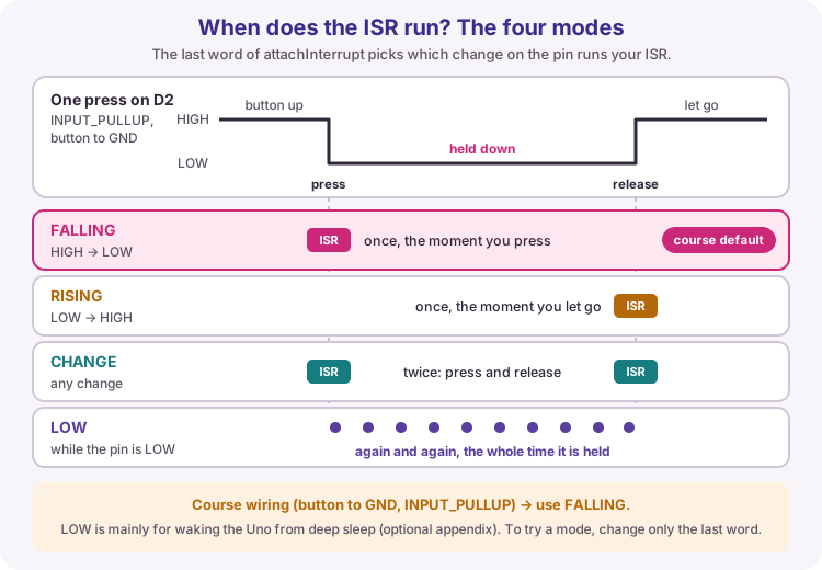
The last word in attachInterrupt says which change on the pin runs your ISR. With the course wiring (button to GND, INPUT_PULLUP) the pin reads HIGH while the button is up and LOW while you hold it down. So FALLING - the moment the pin drops from HIGH to LOW - is the moment you press.
To try another mode, change only that last word and upload again.
| Mode | Runs the ISR when | Typical use |
|---|---|---|
| FALLING | the pin goes HIGH to LOW | a press, with a button to GND and INPUT_PULLUP (this course) |
| RISING | the pin goes LOW to HIGH | the release, or the start of a pulse from a sensor |
| CHANGE | the pin changes either way | press and release, or reading an encoder |
| LOW | the pin is LOW - again and again while it stays LOW | waking the Uno from deep sleep (appendix) |
// Same sketch, but run the ISR on press AND release:
attachInterrupt(digitalPinToInterrupt(buttonPin), onButtonEdge, CHANGE);
Three rules for every ISR
An ISR interrupts everything else, so it has to follow three rules.
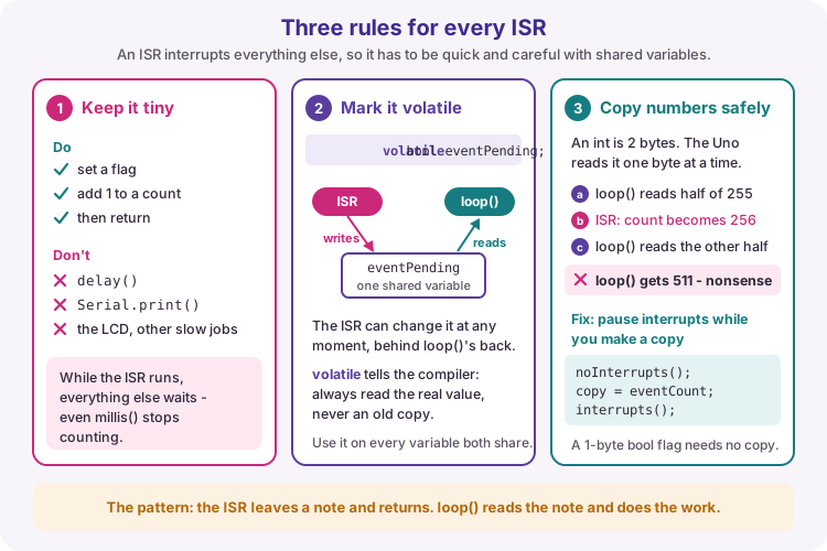
1. Keep it tiny. Set a flag or add 1 to a count, then return. While the ISR runs, the rest of the sketch waits - even millis() stops counting - so never put delay(), Serial.print(), the LCD or other slow jobs inside it.
2. Mark shared variables volatile. A variable that the ISR changes and loop() reads needs the word volatile in front of it. To save time, the compiler sometimes keeps its own quick copy of a variable. volatile tells it: this one can change at any moment, so always read the real value.
3. Copy bigger numbers safely. The Uno works one byte at a time, and an int is two bytes. If the ISR changes the count while loop() is halfway through reading it, loop() gets a mix of the old and new value - for example 511 when the count was going from 255 to 256. So pause interrupts for a moment while you copy the value, then use the copy. A bool flag is a single byte, so it doesn't need this.
volatile unsigned int eventCount = 0;  // 2 bytes, changed by the ISR

void loop() {
  noInterrupts();                       // pause interrupts...
  unsigned int countCopy = eventCount;  // ...copy both bytes...
  interrupts();                         // ...and switch them back on
  // from here on, use countCopy
}
The flag pattern
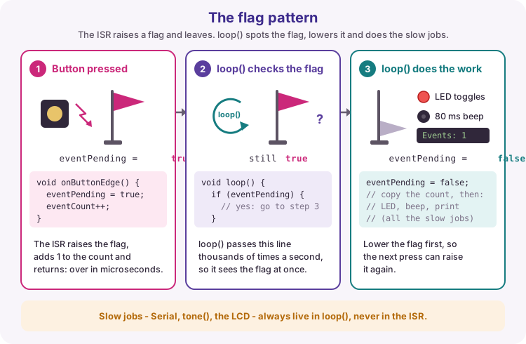
The worked sketch puts these rules together. The ISR does two tiny jobs: it sets eventPending to true (it raises the flag) and adds 1 to eventCount. That's all.
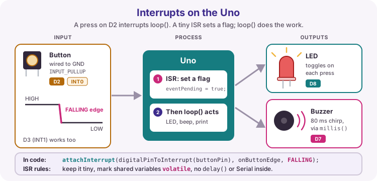
loop() goes past if (eventPending) thousands of times a second. When it finds the flag raised, it lowers it again, takes a safe copy of the count, then does the slow jobs: it toggles the LED, starts a short beep and prints the count. The beep is stopped 80 ms later with millis(), never with delay().
Why one press can count more than once
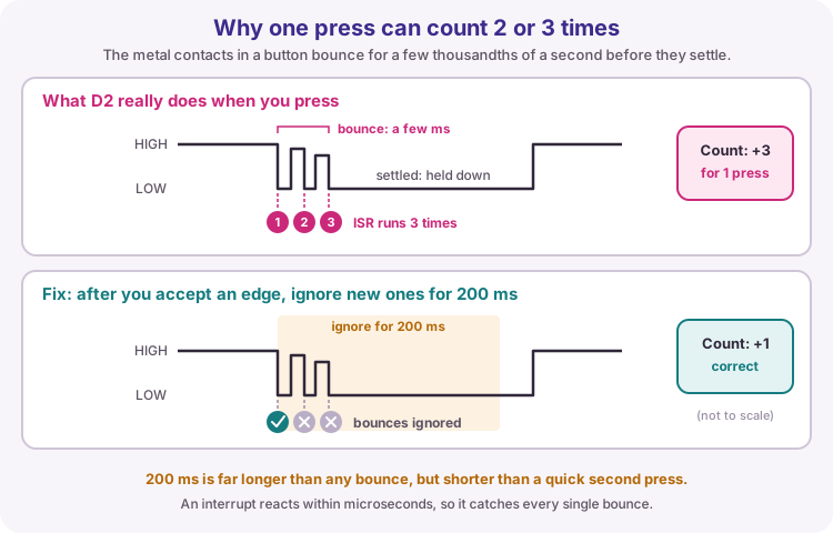
Inside a push-button, two metal contacts snap together. For a few thousandths of a second they bounce - touching, springing apart and touching again - before they settle. You met this in Lesson 10.
An interrupt is fast enough to catch every one of those bounces, and each one is a new HIGH-to-LOW edge, so one press can run the ISR two or three times. The LED may then toggle twice and look as if nothing happened.
The fix is to ignore new edges for a short time after you accept one. 200 ms is far longer than any bounce, but shorter than a quick second press. That is this lesson's challenge.
Build and test in three steps
Add one part at a time and check it before you move on:
1. Button only, from D2 to GND. Run the Step 1 test sketch below and open Serial Monitor at 9600 baud. Pass: tap quickly, once every second or two - the interrupt count goes up for (almost) every tap, while the digitalRead count misses most of them.
2. Add the LED on D8 (through the 330 ohm resistor) and the passive buzzer on D7. Run the worked sketch. Pass: each press toggles the LED, gives a short chirp and prints a bigger count.
3. Press slowly ten times and look at the count. Pass: it says 10. More than 10? That is bounce - fix it with the challenge.
Wiring and safe build sequence
- Button: one leg to D2, the other leg to GND (no resistor needed - the sketch uses INPUT_PULLUP)
- LED: D8 -> 330 ohm resistor -> LED long leg; LED short leg -> GND
- Passive buzzer: + to D7, - to GND
- Appendix templates: use the pin named in each section (D8 for pin-change, LED_BUILTIN for timer and USART, D6/D7 for the comparator)
- Sleep template: the same D2 button; hold it down to wake the Uno
Step 1 test: does loop() notice a quick tap?
Download .inoWhat this sketch is for: Counts quick taps two ways while loop() is stuck in delay(1000): once with digitalRead, once with an interrupt. Button from D2 to GND only. Open Serial Monitor at 9600 baud, tap quickly once, wait for the next line, and repeat. Now and then the interrupt count may jump by 2 - that is bounce, explained above.
const byte buttonPin = 2;           // D2 = interrupt pin INT0

volatile bool tapSeen = false;       // raised by the ISR, read by loop()

int pollCount = 0;                   // taps digitalRead() caught
int interruptCount = 0;              // taps the interrupt caught

void onButtonEdge() {
  tapSeen = true;                    // tiny ISR: just raise the flag
}

void setup() {
  pinMode(buttonPin, INPUT_PULLUP);  // pressed reads LOW
  Serial.begin(9600);
  attachInterrupt(digitalPinToInterrupt(buttonPin), onButtonEdge, FALLING);
  Serial.println("Tap the button quickly, once every second or two.");
}

void loop() {
  // Polling: look at the pin once, right now
  if (digitalRead(buttonPin) == LOW) {
    pollCount++;
  }

  // Interrupt: did the ISR raise the flag since the last pass?
  if (tapSeen) {
    tapSeen = false;
    interruptCount++;
  }

  Serial.print("digitalRead saw: ");
  Serial.print(pollCount);
  Serial.print("   interrupt saw: ");
  Serial.println(interruptCount);

  delay(1000);                       // busy for a second, not looking at D2
}
How the code works
- digitalRead(buttonPin) looks at D2 only once per pass of loop(), so it only counts a tap if you happen to be holding the button at that moment.
- The interrupt is watching all the time, even during delay(1000). The ISR raises tapSeen, and loop() counts it on its next pass.
- Because tapSeen is just true or false, several taps in the same second count as one - tap once, then wait for the next line.
Worked sketch
Download .ino// Each press on D2 toggles the LED, gives a short beep and prints a count.
// The ISR only raises a flag and counts. loop() does all the slow jobs.
const byte buttonPin = 2; // D2 = interrupt pin INT0
const byte ledPin = 8;
const byte buzzerPin = 7;
// Shared with the ISR, so they must be volatile
volatile bool eventPending = false; // the flag: true means "a press happened"
volatile unsigned int eventCount = 0; // how many times the ISR has run
// Used only by loop()
bool ledOn = false;
bool beeping = false;
unsigned long beepStart = 0;
const unsigned long beepMs = 80; // beep length in milliseconds
// The ISR: keep it tiny
void onButtonEdge() {
eventPending = true;
eventCount++;
}
void setup() {
pinMode(buttonPin, INPUT_PULLUP); // pressed reads LOW
pinMode(ledPin, OUTPUT);
pinMode(buzzerPin, OUTPUT);
Serial.begin(9600);
// Run onButtonEdge the moment D2 falls from HIGH to LOW (a press)
attachInterrupt(digitalPinToInterrupt(buttonPin), onButtonEdge, FALLING);
}
void loop() {
if (eventPending) {
// Lower the flag and copy the count, with interrupts paused for a moment
noInterrupts();
eventPending = false;
unsigned int countCopy = eventCount;
interrupts();
// Now the slow jobs, safely outside the ISR
ledOn = !ledOn;
digitalWrite(ledPin, ledOn);
tone(buzzerPin, 1200); // start the beep...
beepStart = millis();
beeping = true;
Serial.print("Events: ");
Serial.println(countCopy);
}
// ...and stop it 80 ms later, without delay()
if (beeping && millis() - beepStart >= beepMs) { // rollover-safe, as in Lesson 11
noTone(buzzerPin);
beeping = false;
}
}How the code works
- The ISR onButtonEdge() does only two tiny jobs: it raises the flag (eventPending = true) and adds 1 to eventCount.
- eventPending and eventCount are volatile because both the ISR and loop() use them.
- attachInterrupt(digitalPinToInterrupt(buttonPin), onButtonEdge, FALLING) runs the ISR the moment D2 drops from HIGH to LOW - a press, with INPUT_PULLUP.
- In loop(), noInterrupts() and interrupts() pause the ISR for a moment while the flag is lowered and the two-byte count is copied, so the count can't change halfway through.
- The LED, tone() and Serial all run in loop(), outside the ISR.
- The beep starts with tone() and stops 80 ms later when millis() - beepStart >= beepMs, so loop() never waits in delay().
Test and record evidence
Practical evidence checklist
Common faults and checks
- Nothing happens when you press: check the button goes from D2 to GND (not 5V), pinMode is INPUT_PULLUP, and attachInterrupt uses digitalPinToInterrupt(buttonPin).
- It works with digitalRead on another pin but not with attachInterrupt: on the Uno only D2 and D3 can use attachInterrupt.
- The count goes up by 2 or 3 per press: that is bounce, not a wiring fault. Do the challenge.
- The sketch freezes or behaves strangely: look for delay(), Serial or other slow code inside the ISR and move it to loop().
- loop() never notices the press: check the shared variable is declared volatile and that you lower the flag after you handle it.
- The count sometimes shows a strange number: copy two-byte values between noInterrupts() and interrupts().
- Appendix - USART template silent: don't also call Serial.begin in the same sketch.
- Appendix - pin-change fires often: it runs on press and release, and on every watched pin in the group; watch only the pin you need.
- Appendix - the Uno never wakes from POWER-DOWN: D2/D3 must be set to LOW to wake it, not FALLING.
- Appendix - USB current barely drops in sleep: that is normal for a full Uno board; only a bare chip drops to microamps.
Check your understanding
Q1. What is the difference between polling and an interrupt?
Show answer
Polling: loop() checks the pin itself with digitalRead, so it only sees the button when that line runs. Interrupt: the hardware watches the pin and runs your ISR the moment the event happens.
Q2. Which Uno pins can use attachInterrupt?
Show answer
Only D2 (INT0) and D3 (INT1).
Q3. Why wrap the pin number in digitalPinToInterrupt()?
Show answer
It turns the pin number into the interrupt number the chip uses, so you don't have to remember it.
Q4. With a button to GND and INPUT_PULLUP, which mode means 'the moment it is pressed'?
Show answer
FALLING - the pin drops from HIGH to LOW when you press.
Q5. What should an ISR do?
Show answer
Only something tiny, such as raising a flag or adding 1 to a count, then return.
Q6. Why must Serial.print and delay stay out of the ISR?
Show answer
They are slow and rely on other interrupts, which are paused while the ISR runs, so they can hang or hold up the whole sketch. Do them in loop().
Q7. Why is a variable shared by the ISR and loop() marked volatile?
Show answer
So the compiler always reads its real value - the ISR can change it at any moment.
Q8. Why copy eventCount between noInterrupts() and interrupts()?
Show answer
An unsigned int is 2 bytes. Without the pause, the ISR could change it halfway through the copy, and loop() would get a mix of the old and new value.
Q9. Why can one press count two or three times?
Show answer
The button contacts bounce, making several HIGH-to-LOW edges, and the interrupt catches every one.
Q10. Optional appendix: after sleep_cpu() wakes the Uno, what runs next?
Show answer
The next line after sleep_cpu(). setup() does not run again unless the board resets.
Q11. Optional appendix: why does a USB Uno still draw tens of mA in power-down?
Show answer
Other parts of the board - the USB-serial chip, the regulator and the LEDs - keep drawing current. Only the bare ATmega328P drops to microamps.
Other interrupt sources (a map)
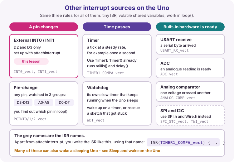
The ATmega328P chip on the Uno has many more interrupt sources than D2 and D3. The templates below give a short, working sketch for each. They set the chip's registers directly (names like PCICR and TCCR1B, from the ATmega328P datasheet), so you don't need to understand every line: upload one, see it work, then change one thing at a time.
The same three ISR rules apply to all of them.
Pin-change interrupt
Pin-change interrupts work on any pin, but the chip watches pins in three groups: D8-D13 (PCINT0), A0-A5 (PCINT1) and D0-D7 (PCINT2). You switch a group on in PCICR, then pick the pins to watch in that group's mask, PCMSK0, PCMSK1 or PCMSK2.
Two differences from attachInterrupt: the ISR runs on any change (press and release), and it doesn't tell you which pin changed - read the pins in loop() if you need to know.
Template: watch a button on D8.
volatile bool edgePending = false;

// Runs when a watched pin in the D8-D13 group changes
ISR(PCINT0_vect) {
  edgePending = true;
}

void setup() {
  pinMode(8, INPUT_PULLUP);
  PCICR |= (1 << PCIE0);     // switch on pin-change for the D8-D13 group
  PCMSK0 |= (1 << PCINT0);   // in that group, watch only D8
  Serial.begin(9600);
}

void loop() {
  if (edgePending) {
    edgePending = false;
    Serial.println("D8 changed");
  }
}
Timer interrupt
A timer interrupt runs your ISR at a steady rate, like a metronome. The Uno has three timers. Timer0 already runs millis() and delay(), so leave it alone and use Timer1. Timer1 is also used by the Servo library and by PWM on D9 and D10, so don't combine them with this template.
Template: Timer1 ticks once a second (16 MHz clock divided by 1024, compare value 15624) and loop() toggles the built-in LED.
volatile bool tickPending = false;

// Runs once a second
ISR(TIMER1_COMPA_vect) {
  tickPending = true;
}

void setup() {
  pinMode(LED_BUILTIN, OUTPUT);

  noInterrupts();            // pause interrupts while setting up Timer1
  TCCR1A = 0;                // clear the Timer1 settings
  TCCR1B = 0;
  TCNT1 = 0;                 // start counting from 0
  OCR1A = 15624;             // 16 MHz / 1024 = 15625 counts per second
  TCCR1B |= (1 << WGM12);    // CTC mode: start again from 0 after OCR1A
  TCCR1B |= (1 << CS12) | (1 << CS10);  // divide the clock by 1024
  TIMSK1 |= (1 << OCIE1A);   // run the ISR each time the count reaches OCR1A
  interrupts();
}

void loop() {
  if (tickPending) {
    tickPending = false;
    digitalWrite(LED_BUILTIN, !digitalRead(LED_BUILTIN));
  }
}
USART receive interrupt
The USART is the hardware behind Serial. It can interrupt each time a byte arrives. This template sets the USART up itself, so don't use Serial.begin or Serial.read in the same sketch - they share the hardware.
Template: 9600 baud on the Uno's USB port. Send 1 or 0 from Serial Monitor to switch LED_BUILTIN on or off.
volatile char lastChar = 0;
volatile bool charPending = false;

// Runs each time a byte arrives
ISR(USART_RX_vect) {
  lastChar = UDR0;           // read the byte (this also clears the interrupt)
  charPending = true;
}

void setup() {
  pinMode(LED_BUILTIN, OUTPUT);
  UBRR0H = 0;
  UBRR0L = 103;              // 9600 baud with a 16 MHz clock
  UCSR0B = (1 << RXEN0) | (1 << RXCIE0);   // receiver on, interrupt on each byte
  UCSR0C = (1 << UCSZ01) | (1 << UCSZ00);  // 8 data bits
}

void loop() {
  if (charPending) {
    noInterrupts();
    char c = lastChar;
    charPending = false;
    interrupts();
    digitalWrite(LED_BUILTIN, c == '1');
  }
}
ADC conversion interrupt
analogRead() waits about 0.1 ms for each reading. Instead, you can start a reading, carry on with other work, and let the ADC interrupt you when the result is ready.
Template: read A0. The ISR saves the result; loop() prints it and starts the next reading.
volatile int adcValue = 0;
volatile bool adcReady = false;

// Runs when a reading is finished
ISR(ADC_vect) {
  adcValue = ADC;            // the 10-bit result, 0 to 1023
  adcReady = true;
}

void setup() {
  Serial.begin(9600);
  ADMUX = (1 << REFS0);      // 5 V reference, input A0
  ADCSRA = (1 << ADEN) | (1 << ADIE) | (1 << ADPS2) | (1 << ADPS1) | (1 << ADPS0);  // ADC on, interrupt on, clock / 128
  ADCSRA |= (1 << ADSC);     // start the first reading
}

void loop() {
  if (adcReady) {
    noInterrupts();          // adcValue is 2 bytes: copy it safely
    int value = adcValue;
    adcReady = false;
    interrupts();
    Serial.println(value);
    ADCSRA |= (1 << ADSC);   // start the next reading
  }
}
Analog comparator interrupt
The analog comparator compares two voltages: D6 (AIN0) against D7 (AIN1). It can interrupt whenever one rises above or drops below the other - a very fast threshold check.
Template: print a line each time the comparison flips. D7 is the buzzer pin in the worked sketch, so take the buzzer off first, and keep both inputs between 0 and 5 V.
volatile bool comparePending = false;

// Runs each time the comparison flips
ISR(ANALOG_COMP_vect) {
  comparePending = true;
}

void setup() {
  Serial.begin(9600);
  ADCSRB &= ~(1 << ACME);    // compare D6 (AIN0) with D7 (AIN1)
  ACSR = (1 << ACIE);        // interrupt whenever the result flips
}

void loop() {
  if (comparePending) {
    comparePending = false;
    Serial.println("Comparator flipped");
  }
}
Watchdog interrupt
The watchdog is a separate slow timer with its own clock, so it keeps running even in the deepest sleep. It can reset the Uno, or just raise an interrupt. Interrupt mode is handy for waking up on a timer; reset mode can rescue a sketch that has got stuck.
Template: a watchdog interrupt about once a second. The settings must be unlocked and changed in two quick steps, which is why the setup lines are in that order.
#include <avr/wdt.h>

volatile bool wdtPending = false;

// Runs about once a second
ISR(WDT_vect) {
  wdtPending = true;
}

void setup() {
  Serial.begin(9600);
  noInterrupts();
  MCUSR &= ~(1 << WDRF);                  // clear any earlier watchdog reset
  WDTCSR |= (1 << WDCE) | (1 << WDE);     // step 1: unlock the settings
  WDTCSR = (1 << WDIE) | (1 << WDP2) | (1 << WDP1);  // step 2: interrupt only, about 1 s
  interrupts();
}

void loop() {
  if (wdtPending) {
    wdtPending = false;
    Serial.println("Watchdog tick");
  }
}
Sleep and wake on the Uno
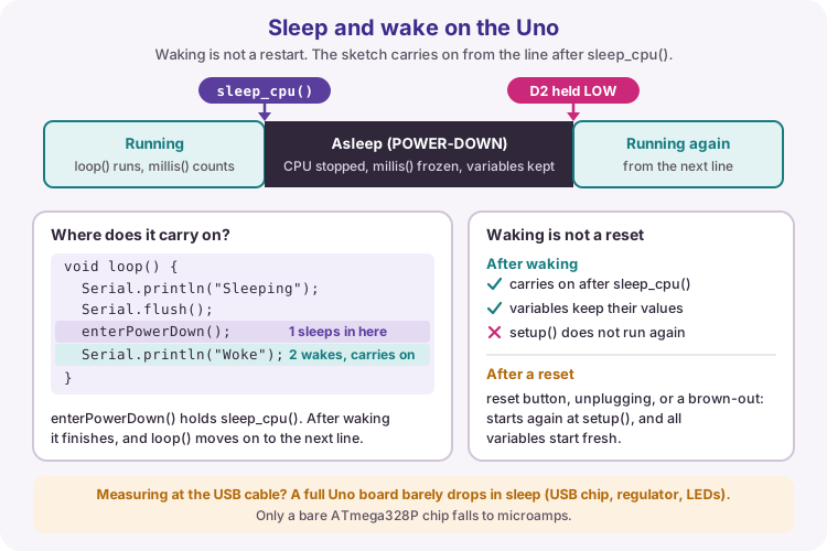
Sleep stops most of the chip to save power until an interrupt wakes it. You pick a sleep mode with set_sleep_mode() from avr/sleep.h, then call sleep_cpu(). The two you will use most:
IDLE - the lightest sleep. The CPU stops, but timers keep running, so millis() still counts. Almost any interrupt wakes it.
POWER-DOWN - the deepest sleep. Almost everything stops, including Timer0, so millis() freezes until the Uno wakes. Only a few sources can wake it: D2/D3 set to LOW (not FALLING or RISING), pin-change interrupts, and the watchdog.
Waking is not a restart. setup() does not run again, and your variables keep their values. The sketch carries on at the line after sleep_cpu(). Only a real reset - the reset button, unplugging the power, or a brown-out - starts again from setup().
Template: a button on D2 to GND with INPUT_PULLUP. The Uno sleeps until you hold the button down.
| Sleep mode | How deep | What can wake it |
|---|---|---|
| SLEEP_MODE_IDLE | Light | Almost any interrupt (timer, USART, external, pin-change, ...) |
| SLEEP_MODE_ADC | Light-medium | ADC finished, and some others |
| SLEEP_MODE_PWR_SAVE | Deeper | Timer2, external or pin-change, watchdog, I2C address match |
| SLEEP_MODE_STANDBY | Deep (clock kept running) | Like power-down, but wakes faster |
| SLEEP_MODE_PWR_DOWN | Deepest | External INT set to LOW, pin-change, watchdog, I2C address match |
#include <avr/sleep.h>

const byte wakePin = 2;

void wakeISR() {
  // Empty on purpose: waking up is the whole job
}

void enterPowerDown() {
  set_sleep_mode(SLEEP_MODE_PWR_DOWN);   // the deepest sleep
  sleep_enable();
  attachInterrupt(digitalPinToInterrupt(wakePin), wakeISR, LOW);  // LOW can wake power-down
  sleep_cpu();                           // sleeps here...
  sleep_disable();                       // ...and carries on here after waking
  detachInterrupt(digitalPinToInterrupt(wakePin));  // stop LOW firing again and again
}

void setup() {
  pinMode(wakePin, INPUT_PULLUP);
  pinMode(LED_BUILTIN, OUTPUT);
  Serial.begin(9600);
  delay(100);
  Serial.println("Running");
}

void loop() {
  Serial.println("Sleeping");
  Serial.flush();                        // finish sending before the chip stops
  digitalWrite(LED_BUILTIN, LOW);

  enterPowerDown();

  digitalWrite(LED_BUILTIN, HIGH);
  Serial.println("Woke - carried on after sleep_cpu()");
  delay(500);
}
Typical current draw (board vs chip)
Sleep only cuts the current used by the chip itself. On a USB Uno board, the USB-serial chip, the regulator and the LEDs keep drawing tens of milliamps, so POWER-DOWN barely changes what you measure at the USB cable. A bare ATmega328P chip on its own (with the brown-out detector off) drops to millionths of an amp.
The figures below are typical, to show the size of the difference - not a promise for every board.
| Mode | Uno board (typical) | ATmega328P chip alone (typical) |
|---|---|---|
| Running normally | about 45 mA to 50 mA | about 12 mA to 15 mA |
| Idle sleep | about 30 mA to 35 mA | about 1.0 mA to 1.5 mA |
| Power-down (deepest sleep) | about 30 mA to 35 mA | about 0.1 uA to 0.5 uA (brown-out detector off) |
SPI and TWI (I2C) interrupts
The Uno also has interrupts for SPI and for TWI (the chip's name for I2C). The SPI and Wire libraries already use them for you, so in Arduino sketches you almost never write these ISRs yourself.
It's enough to recognise the names when you read the datasheet. Use the libraries unless a brief asks for register-level code.
| Source | ISR name | Course approach |
|---|---|---|
| SPI | SPI_STC_vect | Use SPI.h unless told otherwise |
| TWI / I2C | TWI_vect | Use Wire.h unless told otherwise |
Interrupt map at a glance
How each source on this page is switched on, for Uno / ATmega328P coursework.
| Source | How you switch it on | Best for |
|---|---|---|
| External INT0/INT1 | attachInterrupt on D2/D3 | Button and limit-switch edges |
| Pin-change | PCICR + PCMSKx + ISR(PCINTx_vect) | Other pins |
| Timer | TCCRx / TIMSKx + ISR(TIMERn_...) | Steady ticks without delay |
| USART RX | UCSR0B RXCIE0 + ISR(USART_RX_vect) | Serial input byte by byte |
| ADC | ADCSRA ADIE + ISR(ADC_vect) | Analogue reads without waiting |
| Analog comparator | ACSR ACIE + ISR(ANALOG_COMP_vect) | Fast threshold checks |
| Watchdog | WDTCSR WDIE + ISR(WDT_vect) | Timed wake, stuck-sketch rescue |
| Sleep / wake | set_sleep_mode + sleep_cpu() | Saving power; carries on after waking |
| SPI / TWI | Library, or SPI_STC / TWI vectors | Usually SPI.h / Wire.h |