
23. Resistive Sensors, Dividers & the LDR
Turn a resistance change into a voltage the ADC can read, calculate sensor resistance from counts, and switch reliably on light level with hysteresis.
Learning outcomes
- Explain why a resistive sensor needs a fixed resistor to form a voltage divider
- Wire an LDR divider into an analogue pin in the course order (fixed resistor to 5 V, sensor to GND)
- Calculate sensor resistance from an ADC reading and check it with a multimeter
- Choose a fixed resistor that gives useful sensitivity at the light level you care about
- Switch an output with separate ON and OFF thresholds so it does not chatter
Parts and preparation
Uno, LDR, 10 kΩ fixed resistor, LED with 330 ohm resistor, breadboard, jumper wires and a multimeter.
Before power: inspect wiring, confirm supply voltage and ensure all connected circuits share GND.
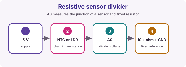
Why resistive sensors need a voltage divider
Arduino analogue pins measure voltage (0 to about 5 V on an Uno), not resistance. An LDR or an NTC thermistor only changes resistance. Place the sensor in series with a known fixed resistor and the mid-point voltage becomes a fraction of the supply that follows the sensor. That mid-point goes to an analogue pin.
This is the same divider idea as the potentiometer in Lesson 14, except one half is fixed and the other half is the sensor.
| What changes | What the Uno measures | What you calculate |
|---|---|---|
| Sensor resistance (ohms) | ADC count 0-1023 (voltage) | Resistance, then a threshold or a temperature |
| Wiring order and Rfixed | Direction of the reading | Which formula to use |
How an LDR works
An LDR (Light Dependent Resistor), usually a cadmium sulphide (CdS) cell, changes resistance with illumination. In the dark it can be megaohms; in bright light a few hundred ohms.
Light frees charge carriers in the photoconductive material, so resistance falls. LDRs are slow (tens to hundreds of milliseconds) and strongly nonlinear, so this course uses them for dark / bright decisions rather than calibrated lux.
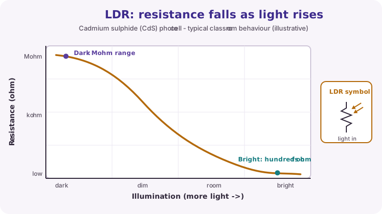
| Condition | Typical LDR resistance (order of magnitude) |
|---|---|
| Dark / covered | Hundreds of kΩ to MΩ |
| Indoor room light | Low kΩ range (part-dependent) |
| Bright / near a lamp | Hundreds of ohms |
Divider calculation (course wiring)
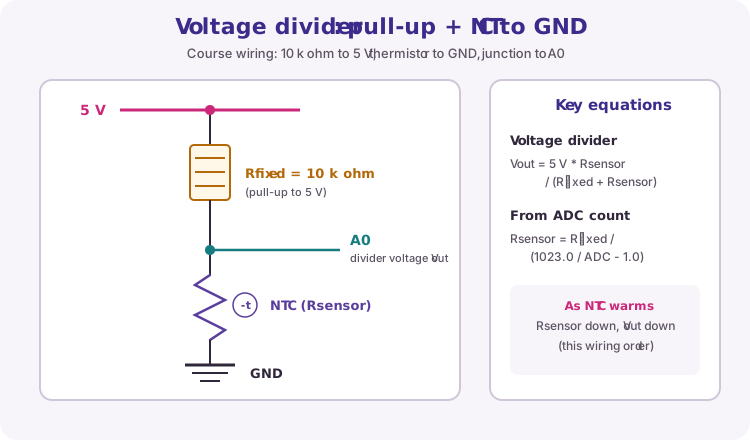
Course wiring puts the fixed resistor to 5 V and the sensor to GND:
5 V → 10 kΩ → junction to A1 → LDR → GND
Junction voltage: Vout = 5 V × Rsensor / (Rfixed + Rsensor). The ADC maps about 0-5 V to 0-1023, so the sensor resistance is:
Rsensor = Rfixed / (1023.0 / ADC - 1.0)
With this order, a darker room raises the LDR resistance, raises Vout and raises the ADC count. Swap the two parts and both the direction and the formula change - always match the code to the physical order.
| ADC reading | Rough meaning (10 kΩ to 5 V, sensor to GND) |
|---|---|
| Near 0 | Junction near GND - shorted sensor, open fixed resistor, or very low Rsensor |
| Near 512 | Rsensor ≈ Rfixed (about half of 5 V) |
| Near 1023 | Junction near 5 V - open sensor, broken GND side, or very high Rsensor |
Worked resistance example
Rfixed = 10000 Ω and analogRead returns 768.
Rsensor = 10000 / (1023.0 / 768 - 1.0) = 10000 / 0.332 ≈ 30 100 Ω - a fairly dim room for a typical LDR.
Vout = 768 / 1023 × 5 V ≈ 3.75 V. Measure the junction with your multimeter: if it reads 3.75 V but Serial shows a very different count, suspect the code or the pin, not the sensor.
If ADC is 0 or 1023, do not use the formula - it divides by zero or gives nonsense. Treat those readings as a wiring fault.
Choosing the fixed resistor
The divider is most sensitive when Rfixed is close to the sensor resistance at the light level you want to detect. Measure the LDR with the multimeter (power off) in the two conditions that matter, then pick a standard value between them.
A 10 kΩ resistor suits most indoor dark / bright decisions. Detecting dusk outdoors may need 100 kΩ; detecting a bright lamp may need 1 kΩ.
| LDR in the condition you care about | Good Rfixed | Effect |
|---|---|---|
| About 1 kΩ (bright) | 1 kΩ | Large ADC change near bright light |
| About 10 kΩ (room light) | 10 kΩ | Large change around normal room light |
| About 100 kΩ (dusk) | 100 kΩ | Large change as it gets dark |
Thresholds and hysteresis
Set thresholds by experiment: cover the LDR and note the count, uncover it under room light and note the count, then choose values between them.
A single threshold chatters: noise near that value flips the output on and off many times a second. Hysteresis uses two thresholds - switch ON above one value, switch OFF only below a lower one. The gap between them must be larger than the noise you see in Serial.
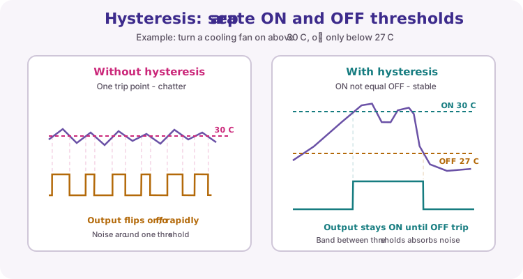
const int darkOn = 700;     // count rises above this: dark
const int brightOff = 600;  // must fall below this to switch off
bool lampOn = false;

if (!lampOn && raw >= darkOn) {
  lampOn = true;
} else if (lampOn && raw <= brightOff) {
  lampOn = false;
}
Check it with the multimeter and scope
Measure the junction voltage with the multimeter while Serial prints the count. Predict the count as V / 5 × 10²³ and compare - they should agree within a few counts. A disagreement points to a wrong pin in the sketch or a supply that is not really 5 V.
On the oscilloscope (DC coupling, 1 V/div) the junction is a steady level that moves as you shade the sensor. Under mains lighting you may see a small 100 Hz ripple: that is the lamp flicker, and it is one reason readings wobble near a threshold.
Wiring and safe build sequence
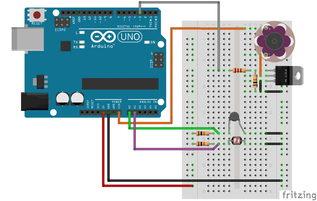
- 5 V -> 10 kΩ -> A1 junction -> LDR -> GND
- D9 -> 330 ohm -> LED anode; LED cathode -> GND (night-light output)
- Multimeter COM to GND, V to the A1 junction for the calibration check
Worked sketch: night light with hysteresis
Download .ino sketchconst byte ldrPin = A1;
const byte lampPin = 9;
const float seriesR = 10000.0; // fixed resistor to 5 V
const int darkOn = 700; // switch the lamp on above this count
const int brightOff = 600; // switch it off only below this count
bool lampOn = false;
unsigned long lastReport = 0;
void setup() {
pinMode(lampPin, OUTPUT);
Serial.begin(9600);
}
void loop() {
int raw = analogRead(ldrPin);
if (raw <= 0 || raw >= 1023) {
digitalWrite(lampPin, LOW);
Serial.println("Divider fault");
delay(500);
return;
}
if (!lampOn && raw >= darkOn) {
lampOn = true;
} else if (lampOn && raw <= brightOff) {
lampOn = false;
}
digitalWrite(lampPin, lampOn);
if (millis() - lastReport >= 500) {
lastReport = millis();
float resistance = seriesR / (1023.0 / raw - 1.0);
Serial.print("ADC ");
Serial.print(raw);
Serial.print(" R ");
Serial.print(resistance, 0);
if (lampOn) {
Serial.println(" ohm lamp ON");
} else {
Serial.println(" ohm lamp OFF");
}
}
}How the code works
- The divider order (10 kΩ to 5 V, LDR to GND) makes the count rise as it gets darker.
- darkOn and brightOff are separate, so the lamp does not flicker when the light sits near one value.
- Readings of 0 or 1023 are treated as a wiring fault and switch the lamp off.
- The Serial report runs every 500 ms with the millis pattern, so the lamp still responds instantly.
Calibration logger: ADC and resistance
Download .ino sketchWhat this sketch is for: Run this first to choose your thresholds. It prints the raw ADC count and the calculated LDR resistance twice a second - cover and uncover the sensor and write the numbers in your logbook.
const float seriesR = 10000.0;  // fixed resistor to 5 V

void setup() {
  Serial.begin(9600);
  Serial.println("LDR on A1 (10k to 5 V, LDR to GND)");
}

void loop() {
  int raw = analogRead(A1);
  if (raw <= 0 || raw >= 1023) {
    Serial.println("Divider fault");
    delay(500);
    return;
  }

  float resistance = seriesR / (1023.0 / raw - 1.0);

  Serial.print("ADC ");
  Serial.print(raw);
  Serial.print("  R ");
  Serial.print(resistance, 0);
  Serial.println(" ohm");
  delay(500);
}
How the code works
- Formula matches course wiring: 5 V -> 10 kΩ -> A1 -> LDR -> GND.
- Record covered, room-light and bright readings, then set darkOn and brightOff between them.
- delay() is fine here - this sketch only logs, it does not control anything.
Test and record evidence
Practical evidence checklist
Common faults and checks
- Count moves the wrong way when you cover the LDR: the resistor and LDR are swapped - match the course order or invert the thresholds.
- Lamp flickers near the switching point: widen the gap between darkOn and brightOff beyond the noise you see in Serial.
- ADC stuck at 0 or 1023: open wire, missing GND or a short across one half of the divider.
- Counts change very little between dark and light: choose a fixed resistor closer to the LDR resistance in the condition you care about.
Check your understanding
Q1. Why does an LDR need a fixed resistor to be read by an Uno?
Show answer
The ADC measures voltage; the LDR only changes resistance, so a divider converts it to a voltage.
Q2. With 10 kΩ to 5 V and the LDR to GND, does the count rise or fall as it gets darker?
Show answer
It rises - the LDR resistance increases, so the junction voltage rises.
Q3. What is Rsensor for this wiring?
Show answer
Rsensor = Rfixed / (1023.0 / ADC - 1.0).
Q4. How do you choose Rfixed for best sensitivity?
Show answer
Pick a value close to the sensor resistance at the light level you want to detect.
Q5. Why use two thresholds instead of one?
Show answer
The gap (hysteresis) stops noise near the switching point from making the output chatter.