
Practical Assessments
How the course is assessed: a code-correction exercise, three practical tasks and a final project, each with a set brief and Competent / Not Yet Competent criteria.
Learning outcomes
- Explain how a Competent or Not Yet Competent result is decided
- Find the brief, criteria and evidence list for each assessment
- Prepare the planning evidence a brief asks for before wiring
- Plan the final project milestones from proposal to demonstration
Parts and preparation
Your bench kit, logbook, multimeter, oscilloscope and the printed brief for the assessment you are sitting.
Before power: inspect wiring, confirm supply voltage and ensure all connected circuits share GND.
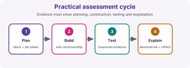
How assessment works on this course
The course is assessed by four practical assessments and an individual final project. Each has a set brief - a realistic job with exact requirements - and a list of criteria. Every criterion is marked Competent or Not Yet Competent on the evidence you show: there are no percentages and no partial marks.
Open the brief before the assessment session, print it if you want a paper copy, and start your planning evidence early. Lesson 12 teaches every document the briefs ask for.
| Assessment | Brief | Sits after |
|---|---|---|
| Code correction | Workshop door-bell indicator with five fault classes | Lesson 12 |
| Task A | Extractor fan speed selector: two buttons, three PWM states | Lesson 15 |
| Task B | Cabinet over-temperature alarm with hysteresis and a transistor-driven buzzer | Lesson 24 |
| Task C | Greenhouse vent controller: DHT11, LDR, servo, LCD and a mode button | Lesson 27 |
| Final project | Your own system, from proposal to demonstration | The last two weeks |
Competent or not yet competent
Each criterion on the grid is marked Competent (C) or Not Yet Competent (NYC). The overall result is Competent only when every criterion is Competent.
Criteria marked with a star are critical: they cover safety and the core purpose of the task, so strong work elsewhere cannot make up for them. An unsafe circuit is Not Yet Competent even if everything else works.
A Not Yet Competent result is not a fail. You receive written feedback listing the criteria still to meet and a reassessment date, normally in the next buffer session. Only those criteria are reassessed.
| Result | What it means | What happens next |
|---|---|---|
| Competent | Every criterion met | Evidence filed; move on |
| Not Yet Competent | One or more criteria not yet met | Feedback, practise, one reassessment of the NYC criteria |
Evidence every assessor expects
A demo that mostly works is not enough. For every practical task you should be able to show:
1. Success criteria and planning produced before wiring 2. Safe wiring: series resistors, common GND, drivers for heavy loads 3. A test table with condition, expected, observed and result 4. At least one fault found and how you fixed it, plus honest unresolved limits 5. An explanation of your decisions when the assessor asks
Use the Lesson 13 habits: measure, do not randomly rewire.
| Artefact | Why it is assessed |
|---|---|
| Success criteria and IPO diagram | Shows you understood the brief |
| Pin and power plan | Prevents pin conflicts and brown-outs |
| Test table | Proves each criterion, not an anecdote |
| Fault log | Shows diagnostic method |
| Oscilloscope and multimeter readings | Proves timing and levels were measured, not assumed |
Code-correction exercise
You are given a faulty door-bell indicator sketch. Write a fault inventory before changing anything, repair the sketch, prove it on the bench and explain the five fault classes: capitalisation, semicolons, braces, = versus ==, and pin mode versus wiring.
Practise first with Code Along Finding & Fixing Faults and with the practice sketch pair on this page.
Practical Task A - Extractor fan speed selector
Two debounced buttons select OFF, LOW (40 % PWM) and HIGH for a fan represented by an LED. A running LED shows when the fan is on, and Serial reports each speed change once. You measure the PWM duty cycle on the oscilloscope as evidence.
| Must demonstrate | Typical evidence |
|---|---|
| Debounce on both buttons | 20 rapid presses give exactly 20 steps |
| States match the state table | State table and live demo |
| PWM at LOW is 40 % | Scope frequency and duty reading |
| Serial only on change | Serial log excerpt |
Practical Task B - Cabinet over-temperature alarm
A thermistor measures cabinet temperature, the LCD shows it to 0.1 °C, and a transistor stage drives a buzzer and LED. The alarm switches on at 30.0 °C and off at 28.0 °C, and a disconnected sensor must switch the alarm on rather than hide the fault.
| Must demonstrate | Typical evidence |
|---|---|
| Calibrated temperature | Calibration table with two reference points |
| Hysteresis | Alarm stays on while cooling from 30 °C to 28 °C |
| Safe alarm drive | Transistor stage in the circuit diagram and BOM |
| Fail-safe sensor fault | SENSOR FAULT on the LCD, alarm on |
Practical Task C - Greenhouse vent controller
A DHT11, an LDR, a servo vent, the I2C LCD and a mode button combine into one controller. You prove each subsystem alone before merging, keep the system responsive with millis(), and inject a sensor failure during the demonstration.
| Subsystem | Acceptance check |
|---|---|
| DHT11 (digital) | Read every 2 s; failed reads never move the vent |
| LDR (analogue) | DAY / NIGHT with hysteresis |
| Servo vent | Own 5 V supply, common GND, pulse width measured |
| LCD and button | Clean rows; button answers within 100 ms |
Final project
Design and build a microcontroller system of your own for a user you can name. It must have at least two inputs (one analogue), an actuator driven safely, a user interface, state logic and non-blocking timing. The extension lessons - ultrasonic, keypad, RFID and SD, interrupts, libraries - are there to help. Each milestone is signed off in your logbook.
| When | Milestone |
|---|---|
| Week 6 | Proposal approved: problem, user, success criteria, block diagram, parts |
| Week 10 | Plan review: pin and power plan, BOM, state table, risks |
| Week 11 | Subsystems proven, then a working prototype |
| Week 12 | Demonstration, 5-minute presentation and portfolio |
Wiring and safe build sequence
- Before any task: pin table, power note and wiring diagram checked by the assessor
- Common GND across the Uno, modules and any external supply
- Series resistors on LEDs; buttons from the pin to GND with INPUT_PULLUP
- Drivers and flyback diodes for motors, relays, solenoids and heavy buzzers
- Short-check with the multimeter before the first power-up
Practice: fixed reference sketch
Download .ino sketch// Code-correction PRACTICE - fixed reference
// Try the faulty practice sketch below before you read this one.
const byte inputPin = 2;
const byte outputPin = 13;
void setup() {
pinMode(inputPin, INPUT_PULLUP); // button to GND
pinMode(outputPin, OUTPUT);
Serial.begin(9600);
}
void loop() {
bool pressed = digitalRead(inputPin) == LOW; // compare, do not assign
if (pressed) {
digitalWrite(outputPin, HIGH);
} else {
digitalWrite(outputPin, LOW);
}
}How the code works
- This is the corrected version of the practice sketch, not the assessment sketch.
- INPUT_PULLUP matches a button wired from the pin to GND, so pressed reads LOW.
- The comparison uses ==; a single = would assign and compile with only a warning.
- Every block is closed and every statement ends with a semicolon.
Practice: faulty sketch
Download .ino sketchWhat this sketch is for: Five fault classes in one short sketch. Write your fault inventory - line, fault, class - before you fix anything, exactly as the assessment asks.
// FAULTY PRACTICE SKETCH - repair before comparing with the fixed reference.
byte InputPin = 2;
byte outputPin = 13;

void setup() {
  PinMode(InputPin, INPUT);
  pinMode(outputPin, OUTPUT)
  Serial.begin(9600);
}

void loop() {
  if (digitalRead(InputPin) = LOW) {
    digitalWrite(outputPin, HIGH);
  else {
    digitalWrite(outputPin, LOW);
  }
}
How the code works
- Look for capitalisation, a missing semicolon, a missing brace, an assignment used as a comparison and a pin mode that does not match the wiring.
- Fix compile faults first, one at a time, then test the behaviour on the bench.
Test and record evidence
Practical evidence checklist
Common faults and checks
- Integration fails: return to the block diagram and prove one subsystem at a time.
- Use compiler messages and measured voltages rather than random rewiring.
- Serial floods: print only on a state change and check the debounce.
- Alarm chatters: use separate on and off thresholds (hysteresis).
- Display blank: run an I2C scanner and confirm the address and wiring.
Check your understanding
Q1. When is the overall result Competent?
Show answer
Only when every criterion on the grid is marked Competent.
Q2. What is a critical criterion?
Show answer
A criterion about safety or the core purpose of the task that cannot be compensated by other work.
Q3. What happens after a Not Yet Competent result?
Show answer
Written feedback and one reassessment of the criteria not yet met.
Q4. What must be produced before wiring?
Show answer
Success criteria, an IPO diagram and a pin and power plan.
Q5. Which Uno pins must Task C keep free for the LCD?
Show answer
A4 (SDA) and A5 (SCL).