
10. Digital Inputs, Pull-Ups & Debouncing
Read buttons reliably: pull-ups and active-low wiring, contact bounce you can see on the oscilloscope, debouncing, and acting once per press.
Learning outcomes
- Explain why an input must not float and how a pull-up fixes it
- Wire a button to GND with INPUT_PULLUP and read pressed as LOW
- Capture contact bounce on the oscilloscope and measure how long it lasts
- Debounce a button with millis() so one press is accepted once
- Detect the press edge and report state changes on Serial without flooding
Parts and preparation
Uno, push button, jumper wires, onboard LED and an oscilloscope.
Before power: inspect wiring, confirm supply voltage and ensure all connected circuits share GND.
Floating inputs
An Uno input pin has a very high impedance - it draws almost no current, so nothing holds it at a level when it is unconnected. A floating input picks up noise from nearby wires and your hand, and reads HIGH or LOW at random.
Try it: set D2 to plain INPUT with a loose jumper attached, print digitalRead(2) in a fast loop, and move your finger near the wire. A pull-up or pull-down resistor fixes the default level so the pin is defined whenever the button is open.
INPUT_PULLUP
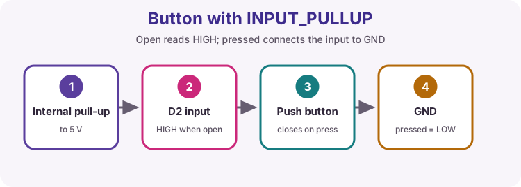
The ATmega328P has internal pull-up resistors of roughly 20-50 kΩ that pinMode(pin, INPUT_PULLUP) switches on. Wire the button from the pin to GND: open reads HIGH, pressed reads LOW. That active-low wiring is the course pattern for every push button.
Pressed current is tiny - about 5 V / 30 kΩ ≈ 0.17 mA. For long cable runs or noisy environments, add an external 10 kΩ pull-up to make the input stiffer.
| Wiring | pinMode | Open reads | Pressed reads |
|---|---|---|---|
| Button to GND (course) | INPUT_PULLUP | HIGH | LOW |
| Button to 5 V + 10 kΩ to GND | INPUT | LOW | HIGH |
| Button to GND, no pull-up | INPUT | Random (floating) | LOW |
See the bounce on the oscilloscope
Put the probe on D2 with the ground clip on GND. Set 1 V/div and 500 µs/div, trigger on a falling edge at about 2.5 V, and use single-shot (single sequence) mode. Press the button once.
Instead of one clean drop from 5 V to 0 V you will usually see several transitions over 0.5 to 5 ms before the line settles. Change the trigger to a rising edge and capture the release too - it often bounces as well.
Record the longest bounce you see across ten presses in your logbook, then choose a debounce time comfortably longer (at least double).
| Scope setting | Value | Why |
|---|---|---|
| Vertical | 1 V/div, DC coupling | 5 V swing fills the screen |
| Horizontal | 500 µs/div | Shows about 5 ms either side of the edge |
| Trigger | Falling edge, 2.5 V, single | Freezes the first press |
Contact bounce
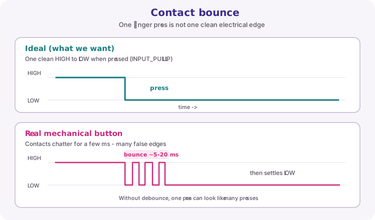
A mechanical button does not snap cleanly between open and closed. As the contacts meet, they bounce for a few milliseconds and the pin voltage chatters between HIGH and LOW.
If your sketch reacts to every raw edge, one physical press can look like many presses. That is why counts race, LEDs flicker, and menus jump.
Software debounce
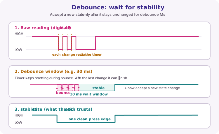
Debouncing accepts a new state only after the raw reading stays unchanged for a short time (debounceMs, often about 20-50 ms).
In this lesson's sketch, every change to the raw reading restarts a millis() timer. When the timer reaches debounceMs and the reading still differs from stableState, the sketch updates stableState. Bounce edges never last long enough to be accepted.
Edge detection
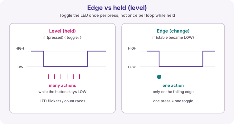
Acting while the button is held (level detection) fires again every loop pass. An event should happen when the stable state changes - for an INPUT_PULLUP button, that is usually the falling edge HIGH to LOW.
This sketch toggles the LED only when stableState becomes LOW, so one press equals one toggle.
Report changes, not levels
Printing the button state on every loop pass floods the Serial Monitor with thousands of identical lines per second and hides the one line you care about. Print only when the stable state changes - the same edge that triggers the action.
The practical assessments mark this directly: Serial must report each state change once, with no flood while a button is held.
Wiring and safe build sequence
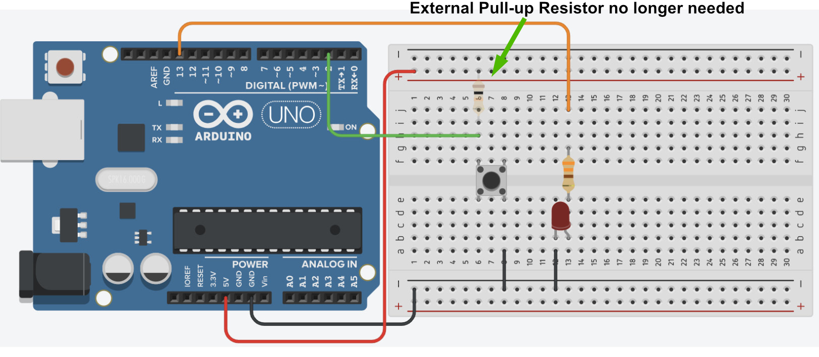
- One button side -> D2
- Opposite button side -> GND
- Configure D2 as INPUT_PULLUP
- Oscilloscope probe on D2, ground clip on GND
Worked sketch
Download .ino sketchconst byte buttonPin = 2;
const unsigned long debounceMs = 30;
bool stableState = HIGH;
bool lastReading = HIGH;
unsigned long changedAt = 0;
unsigned int pressCount = 0;
bool ledOn = false;
void setup() {
pinMode(buttonPin, INPUT_PULLUP);
pinMode(LED_BUILTIN, OUTPUT);
Serial.begin(9600);
Serial.println("Ready");
}
void loop() {
bool reading = digitalRead(buttonPin);
if (reading != lastReading) {
changedAt = millis();
lastReading = reading;
}
if (millis() - changedAt >= debounceMs && reading != stableState) {
stableState = reading;
if (stableState == LOW) {
pressCount++;
ledOn = !ledOn;
digitalWrite(LED_BUILTIN, ledOn);
Serial.print("Press ");
Serial.println(pressCount);
}
}
}How the code works
- The timer restarts whenever the raw reading changes, so bounce never lasts long enough to be accepted.
- Unsigned subtraction remains safe when millis rolls over.
- The LED toggles and the count increases only on the stable pressed edge.
- Serial prints once per press, so holding the button prints nothing extra.
Test and record evidence
Practical evidence checklist
Common faults and checks
- Four-leg buttons connect pairs of legs internally; rotate the button if it always reads pressed.
- Count jumps by two or more per press: debounceMs is shorter than the bounce you measured - increase it.
- Presses are missed when tapped quickly: debounceMs is too long; aim for about twice the measured bounce.
- Nothing prints: check the Serial Monitor is at 9600 baud and the button is on D2 to GND.
- Scope shows no edge: trigger level above 5 V or trigger on the wrong slope.
Check your understanding
Q1. Why must an input not float?
Show answer
Its logic level would be undefined and noise-sensitive.
Q2. With INPUT_PULLUP and a button to GND, what does a press read?
Show answer
LOW.
Q3. What is button bounce?
Show answer
Rapid unintended transitions as mechanical contacts settle.
Q4. How do you choose a debounce time?
Show answer
Measure the longest bounce on the scope and use a time comfortably longer - at least double.
Q5. Why print only when the state changes?
Show answer
Printing every loop floods Serial and hides the events that matter.