
33. MFRC522 RFID Access Log (VMA202)
Identify cards with an MFRC522, decide allow or deny, and append timestamped events to the Velleman VMA202 SD card.
Learning outcomes
- Explain in plain words how an RFID reader reads a card's UID (reader = PCD, card = PICC)
- Name what the VMA202 shield adds: SD card, real-time clock and backup coin cell
- Wire the MFRC522 at 3.3 V through a level shifter, on SS D7 so it does not clash with the SD card on D10
- Test the clock, SD card and reader one at a time before running the full sketch
- Add your own cards to an allow list using the UIDs printed in Serial Monitor
- Write a timestamped ALLOW or DENY line to ACCESS.LOG for every scan
- Time the unlock and the beeps with millis, without delay
- Switch a solenoid lock safely with a MOSFET and a flyback diode
Parts and preparation
Uno; Velleman VMA202 data-logging shield with a CR1220 coin cell fitted; microSD card of 32 GB or smaller, formatted FAT32; MFRC522 RFID reader with at least two cards or fobs; a 4-channel logic-level shifter (or four 1 kΩ resistors); green LED, red LED and two 330 ohm resistors; passive buzzer. For the lock: IRLZ44N MOSFET, 220 ohm and 10 k ohm resistors, 1N4007 diode, a solenoid lock and its own supply. No lock yet? An LED and 330 ohm resistor on D5 stands in for it.
Before power: inspect wiring, confirm supply voltage and ensure all connected circuits share GND.
Libraries for this lesson
In Arduino IDE 2 open Tools → Manage Libraries…. Search by the Library Manager name and install the package by the exact author below. Similar names from other authors can use different APIs and will break the example.
| Include | Library Manager name | Author | Install note |
|---|---|---|---|
SPI.h | SPI | Arduino | Built into the Arduino core. No Library Manager install required. |
MFRC522.h | MFRC522 | GithubCommunity | Install "MFRC522" by GithubCommunity (Miguel Balboa) via Library Manager - not "MFRC522v2", which uses a different header and API. |
SD.h | SD | Arduino | Built-in Arduino library. No Library Manager install required. |
Wire.h | Wire | Arduino | Built into the Arduino core. No Library Manager install required. |
RTClib.h | RTClib | Adafruit | Install via Library Manager for VMA202 RTC timestamps (same as Lesson 26). |
What this project does
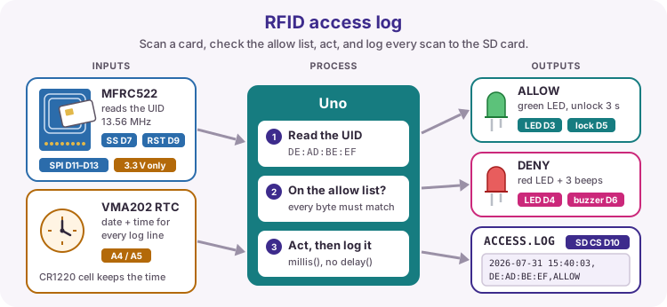
You are building a small door-entry system, like the key-card readers on office or hotel doors. Every card and key fob carries its own ID number, called a UID. Your sketch keeps a short list of allowed UIDs - think of it as the guest list at a door.
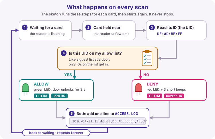
When someone holds a card near the reader, the Uno reads the UID and checks the list. On the list: the green LED lights and the lock opens for three seconds. Not on the list: the red LED lights and the buzzer beeps three times. Either way, the Uno adds one line to a file called ACCESS.LOG on the SD card, with the date and time from the shield's clock - so you can see afterwards who scanned, when, and whether they got in.
It brings together SPI (Lesson 21), the real-time clock (Lesson 26), millis timing (Lesson 11) and safe high-current switching (Lesson 16). Nothing here is new on its own - the new part is making them work together.
How RFID works
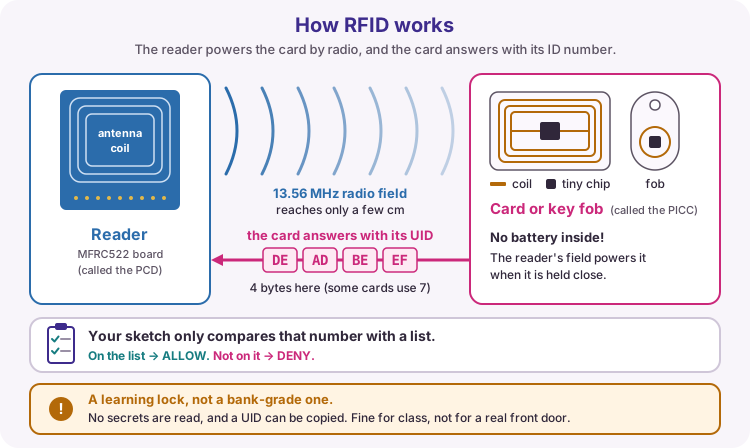
The reader board has a coil of copper track (its antenna) that sends out a weak radio field at 13.56 MHz. A card or fob has no battery. Inside it is a coil and a tiny chip. When you hold it within a few centimetres of the reader, the field powers the chip and the card answers with its UID.
The UID is usually 4 bytes (sometimes 7), shown in hex like DE:AD:BE:EF. Your sketch only compares that number with its list. It does not read anything secret from the card, so this is a learning project, not a bank-grade lock.
Datasheets and the library use two short names you will see in the code: PCD means the reader and PICC means the card.
| Word | Meaning |
|---|---|
| Reader (PCD) | The MFRC522 board wired to the Uno |
| Card or fob (PICC) | What you hold near the reader - no battery inside |
| UID | The card's ID number, 4 or 7 bytes - your allow-list key |
| 13.56 MHz | The radio frequency these kit readers and cards use |
| Range | A few centimetres - hold the card flat over the antenna |
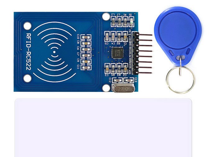
Typical kit reader, card and fob
Most Arduino RFID kits include an MFRC522 (RC522) reader board, a white card and a key fob. The large copper coil area on the board is the antenna - hold tags a few centimetres from that face. The 8-pin header is labelled SDA, SCK, MOSI, MISO, IRQ, GND, RST and 3.3V.
The card and the fob each have their own UID. Enrol one as allowed and keep the other as your 'stranger' to test DENY. Metal desks and stacked cards can stop a read.
Wiring the reader
Two things on this board catch beginners out.
First, the pin labelled SDA is not I2C here. On this board it is the SPI chip-select pin (also called SS). It goes to D7.
Second, the RC522 is a 3.3 V chip. Power it from the Uno's 3.3V pin - never 5 V. The Uno's output pins are 5 V, so the four wires the Uno drives (SS, SCK, MOSI and RST) pass through a level shifter, which turns 5 V signals into 3.3 V signals (Lesson 21). Its HV side connects to the Uno's 5V, its LV side to the Uno's 3.3V, and both GND pins to GND. MISO is the one wire coming back from the reader: 3.3 V is still read as HIGH by the Uno, so it goes straight to D12. No level shifter? Put a 1 kΩ resistor in series in each of the four Uno-driven wires instead.
IRQ is not used - leave it unconnected. In the sketch, MFRC522 rfid(7, 9) tells the library which pins are SS and RST.
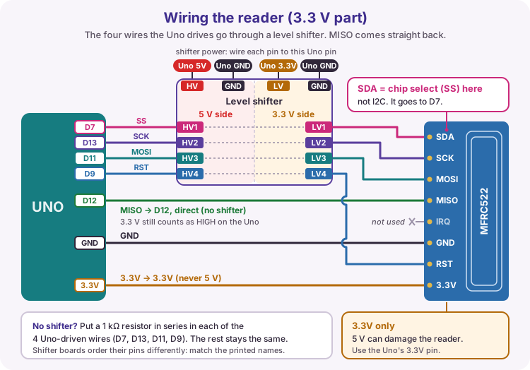
| Reader pin | What it does | Connect to |
|---|---|---|
| SDA (SS) | SPI chip select | D7, through the level shifter |
| SCK | SPI clock | D13, through the level shifter |
| MOSI | Data from Uno to reader | D11, through the level shifter |
| MISO | Data from reader to Uno | D12, direct |
| IRQ | Interrupt (not used) | Leave unconnected |
| GND | Ground | GND |
| RST | Reset the reader | D9, through the level shifter |
| 3.3V | Power | Uno 3.3V - never 5 V |
What the VMA202 adds
The Velleman VMA202 is a data-logging shield: a board that plugs straight on top of the Uno. It adds a microSD card slot, a DS1307 real-time clock (RTC) with a CR1220 coin cell so it keeps the time when the Uno is unplugged, a reset button and a small soldering area you do not need for this build.
Because it plugs on top, its connections are made through the header pins - no wires. That also means it has already taken some pins: D10 to D13 for the SD card and A4/A5 for the clock. The reader, LEDs and buzzer use pins the shield leaves free.
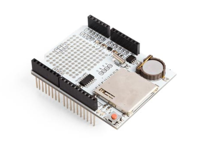
| Feature | What it does in this project |
|---|---|
| SD card slot (SPI) | Holds ACCESS.LOG; chip select is D10 |
| DS1307 clock (I2C) | Gives each log line its date and time, on A4/A5 |
| CR1220 coin cell | Keeps the clock running when the Uno is off |
| Stackable headers | The shield sits on the Uno; wire the reader and outputs to free pins |
| Soldering area | Not needed for this build |
Shared SPI: two chip selects
The SD card and the reader both talk SPI, and they share the same three wires: SCK (D13), MOSI (D11) and MISO (D12). Think of it as one phone line in a house with two phones. Each device also has its own chip-select wire. The Uno pulls one chip select LOW to say "I am talking to you"; the other device sees its own pin HIGH and ignores the traffic.
The shield's SD card is fixed on D10, so the reader gets D7. Many online RFID guides wire the reader to D10 - with the VMA202 fitted, that makes both devices answer at once and neither works. You never switch the chip selects yourself: each library does it inside its own functions.
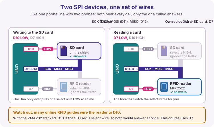
SPI.begin();          // start the shared wires
rfid.PCD_Init();      // the library uses D7 to talk to the reader
SD.begin(10);         // the library uses D10 to talk to the SD card
Course pin map
This map is the one to follow when the VMA202 is stacked. Other diagrams and photos - including the breadboard photo further down - may use different pins.
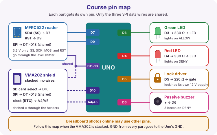
| Function | Uno pin |
|---|---|
| VMA202 SD card chip select | D10 (through the shield) |
| SPI MOSI / MISO / SCK (shared) | D11 / D12 / D13 |
| VMA202 clock SDA / SCL | A4 / A5 (through the shield) |
| Reader SS (labelled SDA) | D7 |
| Reader RST | D9 |
| Reader power | 3.3V (not 5 V) |
| Green LED | D3 |
| Red LED | D4 |
| Lock driver (MOSFET gate) | D5 |
| Buzzer | D6 |
Build it in five tested steps
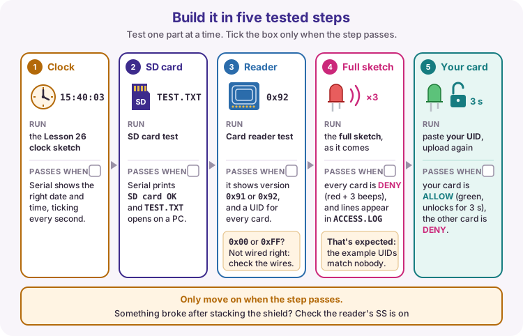
Do not start with the full sketch. If you wire everything and it does not work, you cannot tell which part is wrong. Test one part at a time and only move on when it passes:
1. Clock: run the clock sketch from Lesson 26. Pass: Serial Monitor shows the right time, ticking every second.
2. SD card: run the SD card test sketch (below the wiring list). Pass: "SD card OK", and TEST.TXT opens on a PC.
3. Reader: run the card reader test sketch. Pass: a reader version such as 0x91 or 0x92, and a UID for every card.
4. Full sketch as it comes. Pass: every card shows DENY (red LED, three beeps) and lines appear in ACCESS.LOG. That is expected - the placeholder UIDs match nobody's card.
5. Paste your card's UID into the sketch and upload again. Pass: your card shows ALLOW (green LED, lock opens for 3 s); the other card still shows DENY.
If something that worked stops working after you stack the shield, check the reader is on D7, not D10.
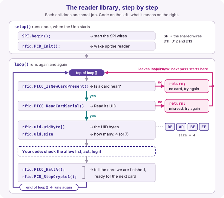
MFRC522 library call sequence
In setup(), SPI.begin() starts the shared wires and rfid.PCD_Init() wakes the reader. That happens once.
In loop(), the sketch asks two questions every pass. rfid.PICC_IsNewCardPresent() asks "is a new card near the reader?" and rfid.PICC_ReadCardSerial() reads its UID. If either answer is no, return ends this pass of loop() early - loop() simply starts again a moment later. That is how the sketch waits for a card without stopping anything else.
After a successful read, rfid.uid.uidByte holds the UID bytes and rfid.uid.size says how many there are (4 or 7). When you have acted and logged, rfid.PICC_HaltA() and rfid.PCD_StopCrypto1() tell the card you are finished. A card that stays on the reader is not read again - take it away and bring it back to scan again.
if (!rfid.PICC_IsNewCardPresent()) return;   // no card: end this pass
if (!rfid.PICC_ReadCardSerial()) return;     // could not read: end this pass
// rfid.uid.uidByte[] now holds the UID, rfid.uid.size how many bytes
rfid.PICC_HaltA();         // finished with this card
rfid.PCD_StopCrypto1();
Enrol UIDs from Serial
The two UIDs in the worked sketch are placeholders. They are not your cards, so every card is denied until you add your own.
Upload the card reader test sketch, open Serial Monitor at 9600 baud and hold a card on the reader. It prints the UID and, on the next line, the same bytes ready to paste - for example {0x4A, 0x7F, 0x12, 0xC3}. The 0x in front of each byte just means the number is written in hex. Copy that line into allowedUid1 in the worked sketch, upload it, and scan the card again.
The number of bytes must match as well: a 4-byte entry never matches a 7-byte card.
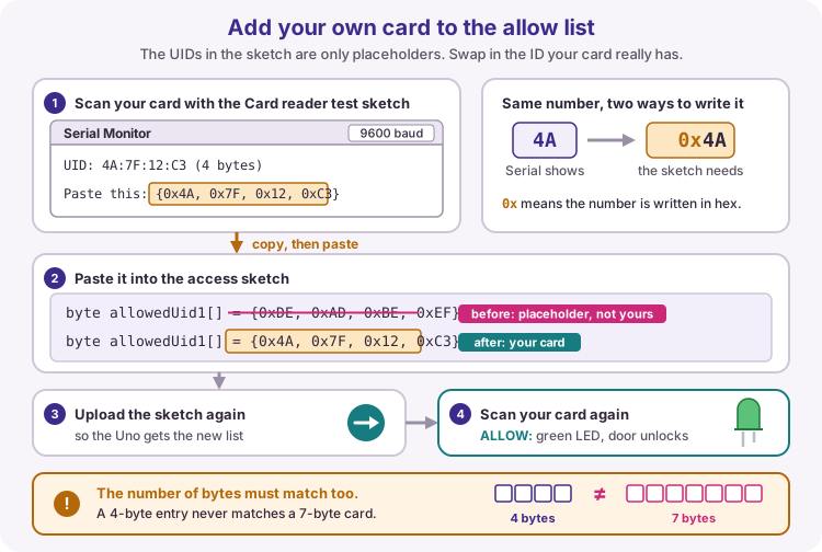
// Card reader test printed:  Paste this: {0x4A, 0x7F, 0x12, 0xC3}
byte allowedUid1[] = {0x4A, 0x7F, 0x12, 0xC3};   // was the placeholder {0xDE, 0xAD, 0xBE, 0xEF}
Allow and deny behaviour
Allowed card: green LED on and the lock driver on for three seconds. Denied card: red LED on and three short beeps; the lock stays shut. Both are written to ACCESS.LOG.
The sketch does not use delay(3000). A delay would freeze the whole Uno for three seconds - no beeps, no card reading. Instead startAllow() switches the outputs on and notes the time with millis(), like starting a kitchen timer. updateOutputs() runs on every pass of loop() and switches them off when the time is up (Lesson 11).
| Result | LEDs and buzzer | Lock |
|---|---|---|
| ALLOW | Green LED for 3 s | Driver on for 3 s, then off |
| DENY | Red LED + 3 short beeps | Stays off |
| Either | One line in ACCESS.LOG | Date and time + UID + result |
Prepare the SD card and ACCESS.LOG
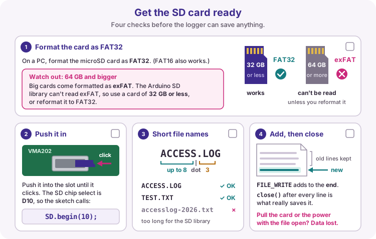
Format the microSD card as FAT32 on a PC before you start (FAT16 also works). Watch out: cards of 64 GB and bigger come formatted as exFAT, which the Arduino SD library cannot read - use a card of 32 GB or less.
Push the card into the VMA202 slot until it clicks. The sketch calls SD.begin(10) because the shield's chip select is D10.
Keep file names short: up to 8 characters, a dot, then up to 3 (ACCESS.LOG, TEST.TXT). Opening with FILE_WRITE adds new lines to the end, so old lines are kept. close() is what actually saves the line onto the card - the sketch closes the file after every scan, so pulling the power loses nothing that was already logged.
ACCESS.LOG line format
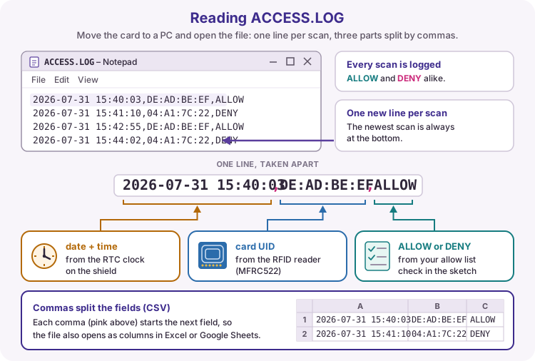
Each scan adds one line, newest at the bottom: 2026-07-31 15:40:03,DE:AD:BE:EF,ALLOW
The date and time come from the shield's clock, the UID from the reader, and ALLOW or DENY from your allow-list check. Commas separate the parts (a CSV line), so the file also opens as neat columns in Excel or Google Sheets.
To check it, switch off, take the card out and open ACCESS.LOG on a PC. If the file is missing, SD.begin failed or no card was scanned. If the time is wrong, see the clock steps in Lesson 26.
Solenoid safety
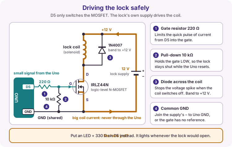
A solenoid lock needs far more current than an Uno pin can give, so the Uno only sends a small signal from D5. A MOSFET does the heavy switching, and the lock gets its own supply. This is the same low-side switch as Lesson 16.
D5 goes through a 220 ohm resistor to the MOSFET gate, and a 10 k ohm resistor from gate to GND keeps the lock off while the Uno is starting up. A diode across the coil (band towards +V) soaks up the voltage spike the coil makes when it switches off. Join the lock supply's GND to the Uno's GND.
No lock yet? Put an LED and 330 ohm resistor on D5 instead - it lights whenever the lock would open, and the sketch does not change.
| Part | Why it is there |
|---|---|
| Separate lock supply | The coil needs far more current than an Uno pin can give |
| MOSFET (IRLZ44N) | A logic-level switch that a 5 V pin can turn fully on |
| 220 ohm gate resistor | Limits the current spike into the gate when D5 switches |
| 10 k ohm pull-down | Holds the gate LOW so the lock stays shut during reset |
| Diode across the coil | Stops the switch-off spike damaging the MOSFET |
| Joined GND | The Uno's signal needs the same reference as the MOSFET |
Assessment evidence
A complete demo pack for this project usually includes:
1. Your pin map showing D10 for the SD card and D7 for the reader
2. Serial Monitor capture from the card reader test with your UIDs
3. Your commented sketch with named pins and your own allow-list bytes
4. An ACCESS.LOG excerpt with both ALLOW and DENY lines
5. A photo or note of the MOSFET and diode lock drive (or the LED stand-in)
6. One fault you found and how you fixed it (often D10 instead of D7, or 5 V on the reader)
Wiring and safe build sequence
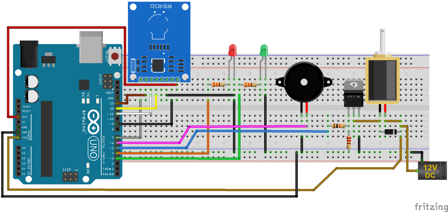
- Fit the CR1220 coin cell, put the microSD card in, then stack the VMA202 on the Uno. The shield connects D10-D13 and A4/A5 itself - no wires
- Level shifter: HV -> Uno 5V, LV -> Uno 3.3V, both GND pins -> GND
- Uno D7 -> shifter HV1, LV1 -> reader SDA (chip select - not D10)
- Uno D13 -> shifter HV2, LV2 -> reader SCK
- Uno D11 -> shifter HV3, LV3 -> reader MOSI
- Uno D9 -> shifter HV4, LV4 -> reader RST
- Reader MISO -> Uno D12 directly (no shifter needed)
- Reader 3.3V -> Uno 3.3V (never 5 V), reader GND -> GND, reader IRQ not connected
- No level shifter? Wire D7, D13, D11 and D9 straight to the reader, each through a 1 kΩ resistor
- Green LED: D3 -> 330 ohm -> LED long leg; short leg -> GND
- Red LED: D4 -> 330 ohm -> LED long leg; short leg -> GND
- Passive buzzer: + -> D6, other leg -> GND
- Lock: D5 -> 220 ohm -> IRLZ44N gate; 10 k ohm gate -> GND; drain -> lock coil -> lock supply +V; source -> GND
- 1N4007 diode across the lock coil, band (cathode) to +V; lock supply GND joined to Uno GND
Step 2 test: SD card
Download .inoWhat this sketch is for: Checks the VMA202 SD card on its own, then writes one line to TEST.TXT. Run it with the shield stacked; the reader can stay wired. Open Serial Monitor at 9600 baud.
#include <SPI.h>
#include <SD.h>

const byte sdCsPin = 10;     // VMA202 SD card chip select (fixed on the shield)
const byte rfidSsPin = 7;    // reader chip select - held HIGH so the reader stays quiet

void setup() {
  Serial.begin(9600);
  pinMode(rfidSsPin, OUTPUT);
  digitalWrite(rfidSsPin, HIGH);

  if (!SD.begin(sdCsPin)) {
    Serial.println("SD card FAILED");
    Serial.println("Check: card pushed in until it clicks, FAT32, 32 GB or smaller");
    return;                  // leave setup early - nothing else can work
  }
  Serial.println("SD card OK");

  File testFile = SD.open("TEST.TXT", FILE_WRITE);   // opens (or creates) the file
  if (!testFile) {
    Serial.println("Could not open TEST.TXT");
    return;
  }
  testFile.println("Hello from the Uno");   // adds one line at the end
  testFile.close();                         // close() saves it onto the card
  Serial.println("Wrote a line to TEST.TXT - open it on a PC to check");
}

void loop() {
  // nothing to repeat - this test runs once
}
How the code works
- SD.begin(10) starts the card using the shield's chip select, D10. It returns false if no card is found or the card is not FAT16/FAT32.
- D7 is set HIGH first so the reader ignores the SPI traffic meant for the SD card.
- return inside setup() just ends setup() early - there is no point writing a file if the card failed.
- Each time you press reset, one more "Hello from the Uno" line is added to TEST.TXT. Several lines on the PC means it is working.
Step 3 test: card reader
Download .inoWhat this sketch is for: Checks the reader on its own and prints the UID of every card you scan, plus a line you can paste straight into the allow list. Use it again whenever you want to add a card. Serial Monitor at 9600 baud.
#include <SPI.h>
#include <MFRC522.h>

const byte rfidSsPin = 7;    // reader SDA/SS pin
const byte rfidRstPin = 9;   // reader RST pin
const byte sdCsPin = 10;     // VMA202 SD chip select - held HIGH so the SD card stays quiet

MFRC522 rfid(rfidSsPin, rfidRstPin);

void setup() {
  Serial.begin(9600);
  pinMode(sdCsPin, OUTPUT);
  digitalWrite(sdCsPin, HIGH);

  SPI.begin();               // start the shared SPI wires
  rfid.PCD_Init();           // wake up the reader

  byte version = rfid.PCD_ReadRegister(rfid.VersionReg);
  Serial.print("Reader version: 0x");
  Serial.println(version, HEX);
  if (version == 0x00 || version == 0xFF) {
    Serial.println("No answer from the reader - check 3.3V, GND, D7 and the SPI wires");
  }
  Serial.println("Hold a card near the reader...");
}

void loop() {
  if (!rfid.PICC_IsNewCardPresent()) return;   // no new card yet - loop runs again
  if (!rfid.PICC_ReadCardSerial()) return;     // card moved away - try again

  // Line 1: the UID as text, e.g. UID: DE:AD:BE:EF (4 bytes)
  Serial.print("UID: ");
  for (byte i = 0; i < rfid.uid.size; i++) {
    if (rfid.uid.uidByte[i] < 0x10) Serial.print("0");   // keep two digits: 0A, not A
    Serial.print(rfid.uid.uidByte[i], HEX);
    if (i < rfid.uid.size - 1) Serial.print(":");
  }
  Serial.print(" (");
  Serial.print(rfid.uid.size);
  Serial.println(" bytes)");

  // Line 2: the same bytes, ready to paste into the allow list
  Serial.print("Paste this: {");
  for (byte i = 0; i < rfid.uid.size; i++) {
    Serial.print("0x");
    if (rfid.uid.uidByte[i] < 0x10) Serial.print("0");
    Serial.print(rfid.uid.uidByte[i], HEX);
    if (i < rfid.uid.size - 1) Serial.print(", ");
  }
  Serial.println("}");
  Serial.println();

  rfid.PICC_HaltA();         // tell the card we are finished
  rfid.PCD_StopCrypto1();    // reset the reader for the next card
}
How the code works
- The version line proves the reader answers. 0x91 or 0x92 is a genuine MFRC522; some clone boards show 0x88 or 0xB2 and still work. 0x00 or 0xFF means no answer - check 3.3V, GND, D7 and the level shifter.
- The two return lines make loop() wait for a card: no card means this pass ends early and loop() runs again.
- rfid.uid.uidByte is an array holding the UID bytes and rfid.uid.size says how many there are. The for loop prints them one by one.
- Serial.print(value, HEX) prints a number in hex. A byte below 0x10 would print as one digit, so a 0 is added first to keep every byte two digits long.
- Expected output for one card: UID: 4A:7F:12:C3 (4 bytes), then Paste this: {0x4A, 0x7F, 0x12, 0xC3}. Your numbers will be different.
- Holding a card still does not repeat the print. Take it away and bring it back to scan again.
Worked sketch: the full access logger
Download .inoWhat this sketch is for: The finished project: reads a card, checks the allow list, drives the LEDs, buzzer and lock, and logs every scan. Run it after the two test sketches above pass. The first time, every card shows DENY - that is expected until you paste your own UIDs.
#include <SPI.h>
#include <MFRC522.h>
#include <SD.h>
#include <Wire.h>
#include <RTClib.h>

// ----- Pins (course pin map) -----
const byte sdCsPin = 10;       // VMA202 SD card chip select (fixed on the shield)
const byte rfidSsPin = 7;      // reader SDA/SS - NOT D10, the SD card uses that
const byte rfidRstPin = 9;     // reader RST
const byte greenLed = 3;
const byte redLed = 4;
const byte lockPin = 5;        // to the MOSFET gate (or a stand-in LED)
const byte buzzerPin = 6;      // passive buzzer

MFRC522 rfid(rfidSsPin, rfidRstPin);
RTC_DS1307 rtc;                // the clock chip on the VMA202

// ----- Allow list -----
// These are placeholders, not your cards. Run the card reader test sketch,
// then paste the {0x.., ...} line it prints for each card you want to allow.
byte allowedUid1[] = {0xDE, 0xAD, 0xBE, 0xEF};
byte allowedUid2[] = {0x01, 0x23, 0x45, 0x67};

// ----- Timing (milliseconds) -----
const unsigned long unlockMs = 3000;   // ALLOW: how long the lock stays open
const unsigned long denyMs = 900;      // DENY: how long the red LED stays on
const unsigned long beepGapMs = 180;   // DENY: time between beeps

// ----- Output state, used by updateOutputs() -----
bool unlocking = false;
unsigned long unlockStart = 0;
bool denying = false;
unsigned long denyStart = 0;
byte beepsLeft = 0;
unsigned long lastBeep = 0;

// true if the card just read has exactly the same bytes as one allow-list entry
bool cardMatches(byte allowed[], byte allowedLength) {
  if (rfid.uid.size != allowedLength) return false;   // a 4-byte entry never matches a 7-byte card
  for (byte i = 0; i < allowedLength; i++) {
    if (rfid.uid.uidByte[i] != allowed[i]) return false;
  }
  return true;
}

// true if the card just read is on the allow list
bool cardIsAllowed() {
  if (cardMatches(allowedUid1, sizeof(allowedUid1))) return true;
  if (cardMatches(allowedUid2, sizeof(allowedUid2))) return true;
  return false;
}

// The card's UID as text, e.g. "DE:AD:BE:EF"
String uidAsText() {
  String text = "";
  for (byte i = 0; i < rfid.uid.size; i++) {
    if (rfid.uid.uidByte[i] < 0x10) text += "0";   // keep two digits: 0A, not A
    text += String(rfid.uid.uidByte[i], HEX);
    if (i < rfid.uid.size - 1) text += ":";
  }
  text.toUpperCase();
  return text;
}

// Adds one line to ACCESS.LOG, e.g. 2026-07-31 15:40:03,DE:AD:BE:EF,ALLOW
void logScan(String uidText, bool allowed) {
  DateTime now = rtc.now();
  char stamp[20];
  snprintf(stamp, sizeof(stamp), "%04d-%02d-%02d %02d:%02d:%02d",
           now.year(), now.month(), now.day(),
           now.hour(), now.minute(), now.second());

  File logFile = SD.open("ACCESS.LOG", FILE_WRITE);   // FILE_WRITE adds to the end
  if (!logFile) {
    Serial.println("Could not open ACCESS.LOG");
    return;
  }
  logFile.print(stamp);
  logFile.print(",");
  logFile.print(uidText);
  if (allowed) {
    logFile.println(",ALLOW");
  } else {
    logFile.println(",DENY");
  }
  logFile.close();             // close() saves the line onto the card
}

void startAllow() {
  digitalWrite(redLed, LOW);
  digitalWrite(greenLed, HIGH);
  digitalWrite(lockPin, HIGH); // unlock
  noTone(buzzerPin);
  denying = false;
  beepsLeft = 0;
  unlocking = true;
  unlockStart = millis();
}

void startDeny() {
  digitalWrite(greenLed, LOW);
  digitalWrite(lockPin, LOW);  // stay locked
  digitalWrite(redLed, HIGH);
  unlocking = false;
  tone(buzzerPin, 1800, 80);   // first beep now...
  beepsLeft = 2;               // ...two more from updateOutputs()
  lastBeep = millis();
  denying = true;
  denyStart = millis();
}

// Called on every pass of loop(): switches outputs off when their time is up
void updateOutputs() {
  unsigned long now = millis();

  if (unlocking && now - unlockStart >= unlockMs) {
    digitalWrite(lockPin, LOW);  // lock again
    digitalWrite(greenLed, LOW);
    unlocking = false;
  }

  if (beepsLeft > 0 && now - lastBeep >= beepGapMs) {
    tone(buzzerPin, 1800, 80);
    beepsLeft--;
    lastBeep = now;
  }

  if (denying && now - denyStart >= denyMs) {
    digitalWrite(redLed, LOW);
    denying = false;
  }
}

void setup() {
  pinMode(greenLed, OUTPUT);
  pinMode(redLed, OUTPUT);
  pinMode(lockPin, OUTPUT);
  pinMode(buzzerPin, OUTPUT);
  digitalWrite(lockPin, LOW);  // start locked
  Serial.begin(9600);

  SPI.begin();
  rfid.PCD_Init();
  Serial.print("Reader version: 0x");
  Serial.println(rfid.PCD_ReadRegister(rfid.VersionReg), HEX);

  Wire.begin();
  if (!rtc.begin()) {
    Serial.println("RTC not found on the VMA202");
  }
  if (!rtc.isrunning()) {      // set the clock once, only if it has stopped
    rtc.adjust(DateTime(F(__DATE__), F(__TIME__)));
  }

  if (SD.begin(sdCsPin)) {
    Serial.println("SD card OK");
  } else {
    Serial.println("SD card FAILED (CS = D10)");
  }
  Serial.println("Ready - scan a card");
}

void loop() {
  updateOutputs();             // runs every pass, card or not

  if (!rfid.PICC_IsNewCardPresent()) return;   // no new card - loop runs again
  if (!rfid.PICC_ReadCardSerial()) return;     // card moved away - try again

  String uidText = uidAsText();
  bool allowed = cardIsAllowed();

  Serial.print("UID ");
  Serial.print(uidText);
  if (allowed) {
    Serial.println(" -> ALLOW");
    startAllow();
  } else {
    Serial.println(" -> DENY");
    startDeny();
  }

  logScan(uidText, allowed);

  rfid.PICC_HaltA();           // tell the card we are finished
  rfid.PCD_StopCrypto1();      // reset the reader for the next card
}
How the code works
- Pins first: every pin has a name, so the rest of the sketch says lockPin instead of 5. Note the reader is on D7 - D10 belongs to the SD card.
- The allow list: byte allowedUid1[] = {0xDE, 0xAD, 0xBE, 0xEF}; is an array of four bytes - one card's UID. These two are placeholders, so every card is denied until you paste your own from the card reader test.
- loop() runs thousands of times a second. It first calls updateOutputs(), then asks the reader for a card. If there is no card, return ends this pass and loop() starts again - so the sketch is always waiting, never stuck.
- cardIsAllowed() checks each allow-list entry with cardMatches(). cardMatches() first checks the length (4 or 7 bytes), then compares the bytes one by one in a for loop. One different byte and the answer is false.
- sizeof(allowedUid1) counts the bytes in that array, so a 7-byte card works too if you paste a 7-byte line.
- uidAsText() turns the bytes into text like DE:AD:BE:EF for Serial Monitor and the log file. String(value, HEX) writes a number in hex and toUpperCase() makes the letters capitals.
- startAllow() and startDeny() switch the outputs on and note the start time with millis(). They do not wait.
- updateOutputs() is the kitchen timer: on every pass it asks "has 3 seconds passed since unlockStart?" and switches the lock off when it has. The beeps work the same way. Writing it as millis() - start >= interval keeps it correct even when millis() rolls over after about 49 days.
- logScan() reads the time from the clock, formats it with snprintf (the same pattern as Lesson 26), opens ACCESS.LOG with FILE_WRITE so the line goes on the end, writes date and time, UID and result, then close() saves it.
- In setup(), rtc.adjust() sets the clock from your PC's time only if the clock has stopped - the set-once pattern from Lesson 26. The reader version line is the same check as the card reader test.
- PICC_HaltA() and PCD_StopCrypto1() finish with the card, so a card left on the reader is logged once, not hundreds of times.
Test and record evidence
Practical evidence checklist
Common faults and checks
- SD card FAILED: card not pushed in until it clicks, or formatted exFAT (64 GB and bigger cards) - use a 32 GB or smaller card formatted FAT32.
- Reader version 0x00 or 0xFF: the reader is not answering. Check 3.3V and GND, the level shifter's HV/LV/GND pins, and that SDA goes to D7.
- Worked alone but stops after stacking the shield: the reader is on D10. Move it to D7 and change rfidSsPin.
- Every card shows DENY: you have not pasted your UID yet, or a byte is copied wrong. Run the card reader test and paste its line exactly; check 4 vs 7 bytes.
- A card on the reader is not read again: that is normal. Take it away and bring it back.
- The same card logs many lines: PICC_HaltA() and PCD_StopCrypto1() are missing from the end of loop().
- Lock is weak or the Uno resets when it clicks: the lock needs its own supply, a diode across the coil and a joined GND.
- Wrong date or time in ACCESS.LOG: fit or replace the CR1220 cell and set the clock once as in Lesson 26.
Check your understanding
Q1. In plain words, what is a UID?
Show answer
The card's own ID number (usually 4 or 7 bytes). The sketch compares it with the allow list.
Q2. What do PCD and PICC mean in this lesson?
Show answer
PCD is the reader (MFRC522); PICC is the card or fob.
Q3. Which VMA202 pin is SD chip select?
Show answer
D10.
Q4. Why must the reader's SS avoid D10 when the VMA202 is stacked?
Show answer
D10 is already the SD card's chip select. Both devices would answer at once on the shared SPI wires.
Q5. What voltage powers the MFRC522, and why do four of its wires go through a level shifter?
Show answer
3.3 V. The Uno's outputs are 5 V, so SS, SCK, MOSI and RST are shifted down to 3.3 V. MISO comes from the reader and goes straight to the Uno.
Q6. On the MFRC522 module, what does the SDA label mean?
Show answer
SPI chip select (SS), not I2C data.
Q7. Why does every card show DENY the first time you run the full sketch?
Show answer
The allow list still holds placeholder UIDs. Paste your own card's UID from the card reader test.
Q8. What three parts go in each ACCESS.LOG line?
Show answer
Date and time, the card's UID, and ALLOW or DENY.
Q9. Why call PICC_HaltA and PCD_StopCrypto1 after a read?
Show answer
To finish with that card, so a card left on the reader is not read over and over and the next card can be detected.
Q10. Why use millis for the 3 s unlock instead of delay(3000)?
Show answer
delay would freeze loop for 3 seconds - no card reading and no beeps. millis lets loop keep running while the timer counts.