19. Stepper Motors & the Stepper Library
Move a geared 28BYJ-48 stepper a counted number of steps with the built-in Stepper library, see the coil sequence on the scope, and understand why steppers can lose position.
Learning outcomes
- Compare stepper and brushed DC motor behaviour
- Explain open-loop stepping, steps per revolution and missed-step risk
- Wire a 28BYJ-48 through a ULN2003 board with its own 5 V supply and a common GND
- Use the Stepper library to move a set number of steps in either direction at a chosen speed
- Measure the coil drive sequence on the oscilloscope
Parts and preparation
Shared station (two in the class): Uno, 28BYJ-48 5 V geared stepper, ULN2003 driver board, separate 5 V supply rated at 1 A or more, jumper wires and an oscilloscope.
Before power: inspect wiring, confirm supply voltage and ensure all connected circuits share GND.
Libraries for this lesson
In Arduino IDE 2 open Tools → Manage Libraries…. Search by the Library Manager name and install the package by the exact author below. Similar names from other authors can use different APIs and will break the example.
| Include | Library Manager name | Author | Install note |
|---|---|---|---|
Stepper.h | Stepper | Arduino | Built into the Arduino IDE. No Library Manager install required. |

Stepper vs brushed DC
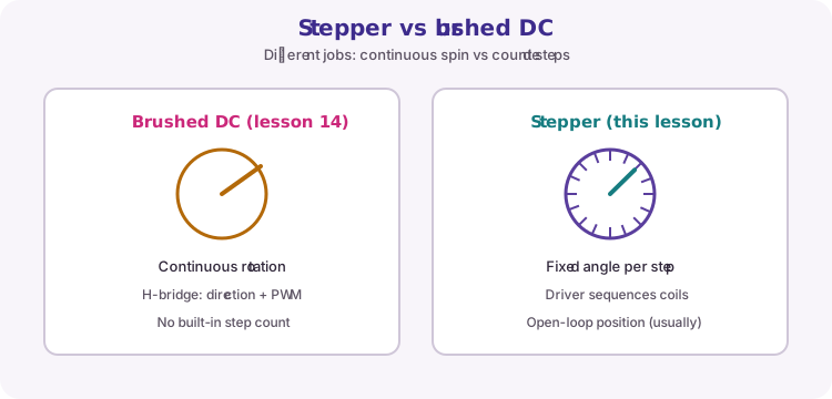
A brushed DC motor (Lesson 18) spins continuously; an H-bridge sets direction and PWM sets speed. You do not get a free step count.
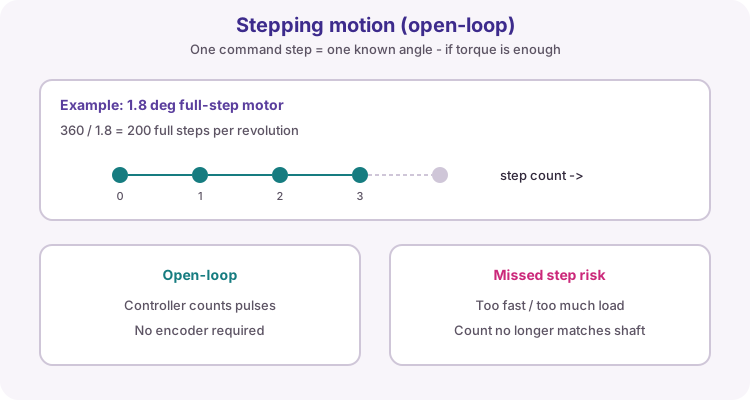
A stepper motor moves in fixed angular increments when its coils are energised in sequence. Count the steps and you know how far the shaft has turned - as long as every commanded step actually happened.
Stepping motion and open-loop control
The 28BYJ-48 has 32 steps per motor revolution and a gearbox of about 64:1, so its output shaft needs about 2048 steps for one full turn in the full-step sequence the Stepper library uses. The gearbox makes it slow but gives useful torque for light mechanisms.
Hobby setups are open-loop: the sketch assumes each step moved the shaft. If the load is too heavy or the speed too high, steps are missed and the software position drifts from reality until you home against a switch or sensor.
| Motor | Steps per output revolution | Note |
|---|---|---|
| 28BYJ-48 (course station) | About 2048 | 32 steps × about 64:1 gearbox |
| NEMA17, 1.8° | 200 full steps | Needs a bipolar driver such as the A4988 |
| Open-loop | - | No encoder; the sketch trusts the step count |
28BYJ-48 and the ULN2003 board
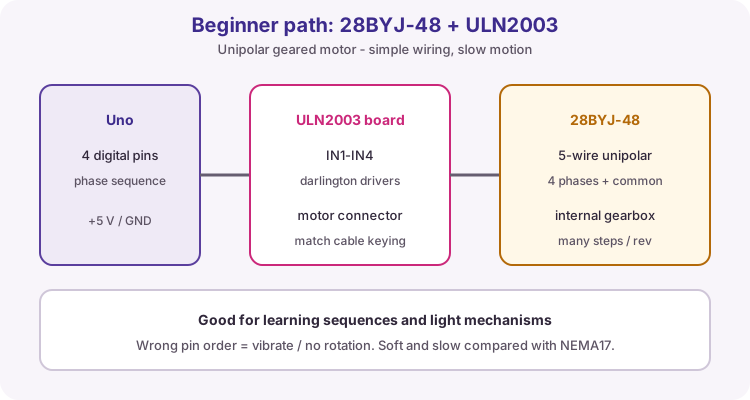
The 28BYJ-48 is a small unipolar stepper with five wires: four coil ends and a common red wire to +5 V. The ULN2003 board is a Darlington transistor array - seven NPN Darlington pairs with built-in flyback diodes - so each Uno pin only switches base current while the board sinks the coil current.
Four LEDs on the board show which inputs are HIGH, which makes the step sequence visible. Power the motor side from a separate 5 V supply and join its GND to the Uno GND.
| ULN2003 pin | Connect to |
|---|---|
| IN1 | D8 |
| IN2 | D9 |
| IN3 | D10 |
| IN4 | D11 |
| + (5-12 V) | Separate 5 V supply + |
| - | Supply GND and Uno GND |
| Motor socket | 28BYJ-48 keyed plug |
The Stepper library
The built-in Stepper library sends the coil sequence for you. Create one Stepper object with the steps per revolution and the four pins, set the speed in revolutions per minute with setSpeed(), then call step(n). A positive n turns one way, a negative n the other.
Pin order matters: for the 28BYJ-48 on a ULN2003 board, give the pins as IN1, IN3, IN2, IN4 (8, 10, 9, 11). With the natural order the motor only buzzes or twitches.
Keep setSpeed() at 15 rpm or below for this motor. Faster than that it stalls and misses steps.
#include <Stepper.h>

const int stepsPerRev = 2048;
Stepper motor(stepsPerRev, 8, 10, 9, 11);   // IN1, IN3, IN2, IN4

void setup() {
  motor.setSpeed(10);        // rpm
}

void loop() {
  motor.step(512);           // quarter turn one way
  delay(1000);
  motor.step(-512);          // quarter turn back
  delay(1000);
}
step() blocks the sketch
step(n) does not return until every step has been sent. At 10 rpm a full turn of 2048 steps takes 6 seconds, and during that time loop() cannot read a button or update a display.
For a responsive sketch, move one step at a time from loop() using the millis pattern from Lesson 11, and keep a variable for how many steps are still to go.
long stepsToGo = 2048;
unsigned long lastStep = 0;
const unsigned long stepIntervalMs = 3;   // about 10 rpm

void loop() {
  if (stepsToGo > 0 && millis() - lastStep >= stepIntervalMs) {
    lastStep = millis();
    motor.step(1);
    stepsToGo--;
  }
  // buttons, Serial and displays still run here
}
Scope the coil sequence
Probe IN1 on channel 1 and IN2 on channel 2 (ground clip on GND), 2 V/div and 5 ms/div, while the motor turns at 10 rpm. The library energises two coils at a time in a four-step pattern, so each input is a square wave that is HIGH for two steps out of four.
At 10 rpm the motor takes 2048 × 10 / 60 ≈ 341 steps per second, about 2.9 ms per step. One four-step cycle is about 11.7 ms, so each input shows roughly 85 Hz at 50 % duty, with IN2 shifted by one step from IN1. Double the speed and the frequency doubles - check it.
| setSpeed() | Steps per second | Coil input frequency |
|---|---|---|
| 5 rpm | ≈ 171 | ≈ 43 Hz |
| 10 rpm | ≈ 341 | ≈ 85 Hz |
| 15 rpm | ≈ 512 | ≈ 128 Hz |
Power, heat and station rules
Each energised coil of a 5 V 28BYJ-48 draws roughly 200 mA, and two are on at once - far more than the Uno 5 V pin should supply for long runs. Use the separate supply and a common GND.
The library leaves the last two coils energised when step() finishes, so a parked motor still draws current and warms up. Write all four pins LOW after a move if the shaft does not need holding torque.
There are two stepper stations in the class. Leave each station exactly as you found it for the next group.
| Station rule | Why |
|---|---|
| Power off before plugging or unplugging the motor | Protects the ULN2003 and the supply |
| Check the keyed plug and IN1-IN4 wiring first | Wrong order only twitches and wastes your slot |
| Run the worked sketch before your own code | Proves the station works |
| Release the coils and unplug the supply when done | Motor stays cool for the next group |
Bigger steppers and STEP/DIR drivers
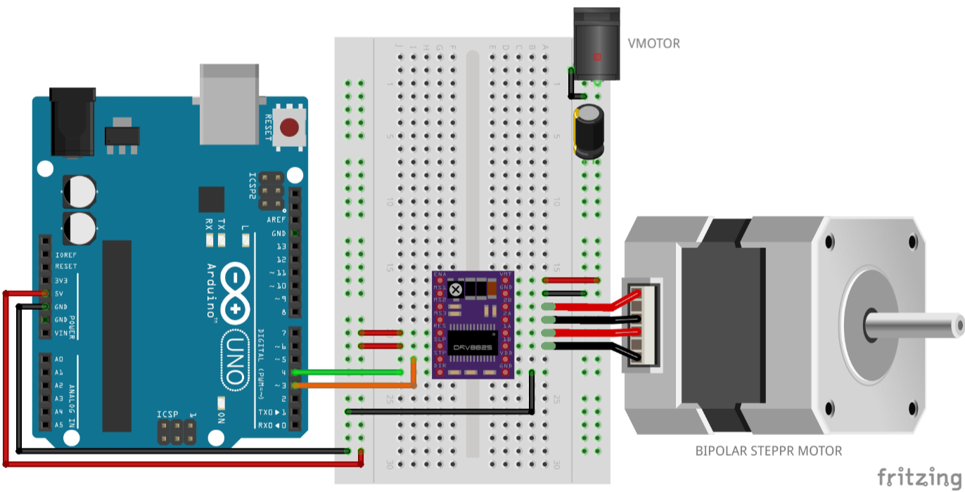
Larger bipolar steppers such as the NEMA17 need a current-limiting driver like the A4988 or DRV8825, controlled with STEP and DIR pins instead of four coil inputs. The optional appendix below covers that path for final projects that need more torque.
Wiring and safe build sequence
- Power off. ULN2003 IN1 -> D8, IN2 -> D9, IN3 -> D10, IN4 -> D11
- ULN2003 + -> separate 5 V supply +; ULN2003 - -> supply GND
- Supply GND -> Uno GND (common ground)
- Plug the 28BYJ-48 into the keyed socket on the ULN2003 board
- Scope channel 1 on IN1, channel 2 on IN2, ground clip on GND
Worked sketch
Download .ino sketch#include <Stepper.h>
const int stepsPerRev = 2048; // 28BYJ-48 output shaft
const byte coilPins[] = {8, 9, 10, 11};
// ULN2003 IN1, IN3, IN2, IN4 - the order the library needs for this motor
Stepper motor(stepsPerRev, 8, 10, 9, 11);
void releaseCoils() {
for (byte i = 0; i < 4; i++) {
digitalWrite(coilPins[i], LOW); // no holding current while parked
}
}
void setup() {
motor.setSpeed(10); // rpm - keep at 15 or below
Serial.begin(9600);
}
void loop() {
Serial.println("Quarter turn forward");
motor.step(stepsPerRev / 4);
releaseCoils();
delay(1000);
Serial.println("Quarter turn back");
motor.step(-stepsPerRev / 4);
releaseCoils();
delay(1000);
}How the code works
- The Stepper object gets the pins in IN1, IN3, IN2, IN4 order - required for the 28BYJ-48 on a ULN2003.
- step(512) is a quarter of 2048 steps; a negative count reverses direction.
- releaseCoils() stops the coils drawing current while the motor waits.
- step() blocks until the move finishes, so the Serial message prints before each move, not during it.
Test and record evidence
Practical evidence checklist
Common faults and checks
- Motor buzzes or twitches but does not turn: pin order in the constructor must be 8, 10, 9, 11.
- Turns the wrong way: swap the sign of the step count rather than rewiring.
- Stalls or misses steps: lower setSpeed() and check the separate supply can deliver 1 A.
- Uno resets when the motor starts: the motor is running from the Uno 5 V pin - use the separate supply with common GND.
- Motor hot when idle: call releaseCoils() after each move.
Check your understanding
Q1. Why can a stepper lose position?
Show answer
It is open-loop: steps are missed if the load or speed is too high, and the sketch does not know.
Q2. About how many steps turn the 28BYJ-48 output shaft once?
Show answer
About 2048 (32 steps × about 64:1 gearing).
Q3. Why does the Stepper constructor use pins 8, 10, 9, 11 for this motor?
Show answer
The library's coil sequence needs IN1, IN3, IN2, IN4 order for a 28BYJ-48 on a ULN2003.
Q4. Why must the motor use a separate supply?
Show answer
Two coils draw roughly 400 mA together - too much for the Uno 5 V pin.
Q5. What is the drawback of motor.step(2048)?
Show answer
It blocks loop() until the whole move finishes.
A4988 path: STEP and DIR
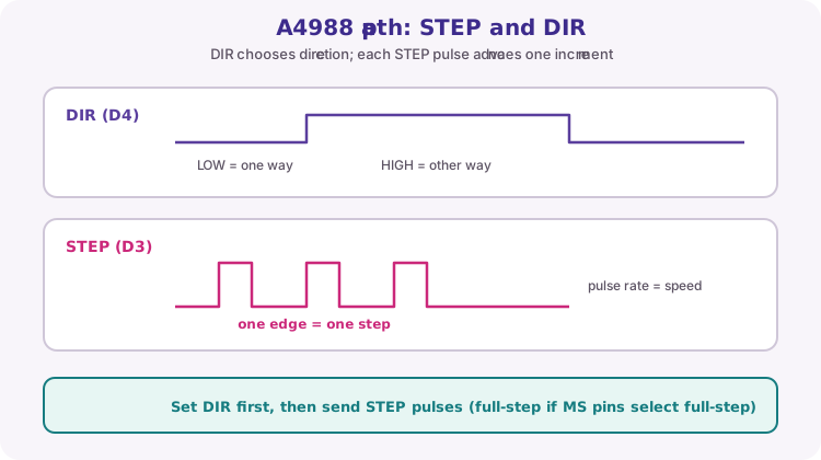
Bipolar drivers such as A4988 or DRV8825 take STEP and DIR logic from the Uno. Set DIR for the desired direction, then pulse STEP. Each rising edge advances one full step or one microstep, depending on the MS1/MS2/MS3 mode jumpers.
Pulse rate controls speed; total pulse count controls distance. A common NEMA17 full-step angle is 1.8 degrees, so 200 full steps make one revolution; microstepping divides each step for smoother motion.
const byte stepPin = 3;
const byte dirPin = 4;

void moveSteps(long steps, bool clockwise) {
  digitalWrite(dirPin, clockwise);
  for (long i = 0; i < steps; i++) {
    digitalWrite(stepPin, HIGH);
    delayMicroseconds(800);
    digitalWrite(stepPin, LOW);
    delayMicroseconds(800);
  }
}
A4988 power, coils and current limit
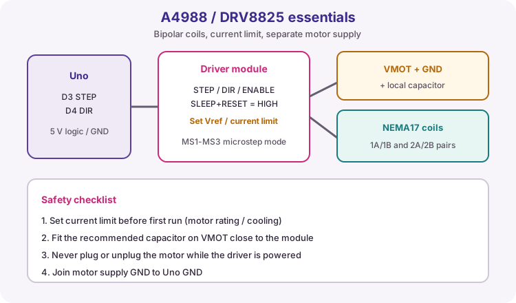
Motor current comes from VMOT on an external supply, not from the Uno. Join grounds. Fit the capacitor recommended by the module close to VMOT.
Identify coil pairs (often by resistance / continuity) and wire them to 1A/1B and 2A/2B. Set the driver's current limit (Vref pot) before the first run to protect the motor and the module. Never connect or disconnect the motor while the driver is powered.
| Connection | Course practice |
|---|---|
| STEP | D3 |
| DIR | D4 |
| SLEEP / RESET | Held HIGH as module docs require |
| VMOT / GND | Motor supply + local capacitor |
| Logic VDD / GND | 5 V and common GND |
| Coils | 1A/1B and 2A/2B pairs |
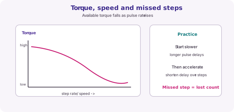
Torque, speed and acceleration
Available torque falls as step rate rises. Starting at a high pulse rate under load causes missed steps. For heavier mechanisms, start with longer delays and shorten them over the first many steps (acceleration).