
12. Planning, Documentation & Evidence
Turn a brief into success criteria, an IPO diagram, truth table and pin plan, then prove the build with a test table and fault log - the evidence every assessment marks.
Learning outcomes
- Rewrite a practical brief as measurable success criteria
- Draw an input-process-output (IPO) block diagram and a truth table for state logic
- Produce a pin and power plan that checks for pin conflicts and current limits
- Write a bill of materials (BOM) with ratings and safety notes
- Record a test table and a fault log that prove each criterion, including what is still unresolved
Parts and preparation
Logbook (or printed templates), Uno, one push button, one LED with 330 ohm resistor, breadboard, jumpers and a multimeter for the worked example.
Before power: inspect wiring, confirm supply voltage and ensure all connected circuits share GND.
Why evidence matters
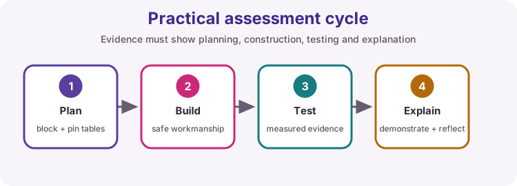
A working demo proves the build worked once, in front of one person. Evidence proves you understood the brief, built it safely and tested it properly - and it is what an assessor can check afterwards.
Every practical assessment on this course marks the planning and documentation as well as the build. This lesson practises each artefact on a small example so that the assessments test your electronics and code, not your paperwork.
| Artefact | When you make it | What it proves |
|---|---|---|
| Success criteria | Before wiring | You understood the brief |
| IPO / block diagram | Before wiring | You know what each part of the system does |
| Truth table / state table | Before coding | The logic is decided, not discovered |
| Pin and power plan | Before wiring | No pin conflicts, no overloaded supply |
| BOM with safety notes | Before wiring | Parts are rated for the job |
| Test table | During and after testing | Each criterion is met, with observed values |
| Fault log | Whenever something fails | You diagnose by method |
From brief to success criteria
A brief describes what someone wants. Success criteria turn it into statements you can test with a yes or no, usually with a number attached. Write them before you wire anything, then judge your own demo against them.
If a criterion cannot fail, it is not a criterion. 'The LED works' cannot fail; 'the LED changes state within 50 ms of a press' can.
| Vague | Measurable |
|---|---|
| The button works | Each press toggles the lamp exactly once, including 20 rapid presses |
| It shows the temperature | LCD row 0 shows temperature to 0.1 °C, updated every 2 s |
| The alarm is reliable | Alarm turns on at 35.0 °C and off at 32.0 °C with no chatter in between |
| It is safe | No I/O pin supplies more than 20 mA; motor runs from its own supply with common GND |
IPO and block diagrams
An input-process-output (IPO) diagram lists every input on the left, the decisions in the middle and every output on the right. It becomes the plan for your functions: readInputs(), updateState(), driveOutputs().
Draw one arrow for each signal and label it with the pin and the signal type (digital, analogue, PWM, I2C).
| Input | Process | Output |
|---|---|---|
| Button on D2 (digital, active-low) | Debounce; toggle lamp state on each press | LED on D9 (digital) |
| - | Report only when the state changes | Serial message at 9600 baud |
Truth tables for state logic
When outputs depend on several inputs or on a remembered state, write the table first. List every combination of inputs, the current state, and what the next state and outputs must be. The table then becomes the if / else if chain or switch in your sketch, and your test table checks each row.
| Button A | Button B | Output state | Status LED | PWM LED |
|---|---|---|---|---|
| Released | Released | OFF | Off | 0 |
| Pressed | Released | LOW | On | 64 |
| Released | Pressed | HIGH | On | 255 |
| Pressed | Pressed | OFF (safety) | Flashing | 0 |
Pin, power and conflict plan
Give every connection a row: pin, direction, signal type, device and note. Then check for conflicts before wiring:
- D0 and D1 are the USB serial link - avoid them. - PWM only works on 3, 5, 6, 9, 10 and 11. - A4 and A5 are the I2C bus - keep them free if a display or RTC is used. - Servo.h disables PWM on pins 9 and 10. - tone() interferes with PWM on pins 3 and 11.
Add a power budget: estimate the current of each load and decide which supply provides it. An I/O pin is a signal, not a supply - keep each below 20 mA and use a driver for anything larger.
| Pin | Mode | Signal | Device | Current / note |
|---|---|---|---|---|
| D2 | INPUT_PULLUP | Digital, active-low | Push button to GND | Pressed = LOW |
| D9 | OUTPUT | Digital | LED + 330 Ω to GND | (5 - 2) / 330 ≈ 9 mA |
| 5 V / GND | Supply | - | Breadboard rails | USB 500 mA budget |
Bill of materials with safety notes
The BOM lists every part with its value and rating, and says why the part is safe in this circuit. Ratings matter for the assessment: a resistor value without a current calculation, or a motor without its supply voltage, is incomplete.
| Qty | Part | Value / rating | Safety note |
|---|---|---|---|
| 1 | Arduino Uno R3 | 5 V logic, 20 mA per pin | Powered from USB only |
| 1 | Red LED | Vf ≈ 2 V, 20 mA max | Series resistor limits current to ≈ 9 mA |
| 1 | Resistor | 330 Ω, 0.25 W | Dissipates ≈ 27 mW - well within rating |
| 1 | Push button | 12 mm tactile | Switches internal pull-up current only (< 1 mA) |
Test tables that prove criteria
Each row tests one criterion under one condition: what you did, what should happen, what actually happened, and pass or fail. Observed values must be real observations - a Serial excerpt, a measured voltage, a scope reading - not a copy of the expected column.
Include at least one failure injection: disconnect a sensor, hold a button, or feed an out-of-range value and record how the system copes.
| # | Condition | Expected | Observed | Result |
|---|---|---|---|---|
| 1 | Power up | Serial: Lamp controller ready: OFF; LED off | Message shown; LED off; D9 = 0.01 V | Pass |
| 2 | Single press | LED on; one 'Lamp ON' line | LED on; one line | Pass |
| 3 | 20 rapid presses | 20 toggles, 20 lines, ends OFF | 21 lines on first try | Fail - see fault log F1 |
| 4 | Button held for 5 s | No repeated messages | One line only | Pass |
| 5 | Failure injection: button wire removed | No toggles, no messages | No change | Pass |
Fault log: resolved and unresolved
Log every fault the moment you see it: symptom, what you suspected, what you measured, what you changed, and the re-test result. Change one thing at a time so the log shows which change fixed it.
Keep a separate list of unresolved limits - things that still do not work perfectly, or would need better parts. Honest unresolved notes are marked as evidence of understanding; claiming a fault-free build is not.
| ID | Symptom | Suspected cause | Measurement / check | Fix | Re-test |
|---|---|---|---|---|---|
| F1 | Extra toggle on rapid presses | Contact bounce | Scope on D2: 2 ms of bounce on release | Debounce time raised from 5 ms to 30 ms | Test 3 passes |
| U1 | Very fast double taps (< 30 ms) are ignored | Debounce window | - | Unresolved: acceptable for a lamp | - |
Staged integration
Never wire a whole system and upload the full sketch first. Prove each subsystem alone with a short test sketch, tick it off, then add the next one. When something breaks after a merge, you know it is the last thing you added.
Keep the checklist in your logbook with the date and a Serial excerpt or photo for each stage - the integrated assessments ask for it.
| Stage | Test sketch proves | Evidence |
|---|---|---|
| 1. Button | D2 reads LOW when pressed, HIGH when released | Serial excerpt |
| 2. Output | D9 turns the LED on and off; 3.0 V across the resistor | Multimeter reading |
| 3. Logic | Toggle and debounce with Serial reports | Test table rows 2-4 |
| 4. Full system | Every success criterion | Complete test table |
Wiring and safe build sequence
- Push button between D2 and GND (INPUT_PULLUP - no external resistor)
- D9 -> 330 ohm -> LED anode; LED cathode -> GND
- Record both connections in a pin table before powering the board
Worked sketch: the documented lamp controller
Download .ino sketch// Lamp controller - the worked documentation example
const byte buttonPin = 2; // INPUT_PULLUP, pressed = LOW
const byte lampPin = 9; // LED via 330 ohm
const unsigned long debounceMs = 30; // fault log F1: raised from 5 ms
bool lampOn = false;
bool lastPressed = false;
unsigned long lastChangeMs = 0;
void setup() {
pinMode(buttonPin, INPUT_PULLUP);
pinMode(lampPin, OUTPUT);
Serial.begin(9600);
Serial.println("Lamp controller ready: OFF");
}
void loop() {
bool pressed = digitalRead(buttonPin) == LOW;
if (pressed != lastPressed && millis() - lastChangeMs >= debounceMs) {
lastChangeMs = millis();
lastPressed = pressed;
if (pressed) {
lampOn = !lampOn;
if (lampOn) {
digitalWrite(lampPin, HIGH);
Serial.println("Lamp ON");
} else {
digitalWrite(lampPin, LOW);
Serial.println("Lamp OFF");
}
}
}
}How the code works
- Pin names and the debounce constant match the pin table and fault log, so the documents and the code agree.
- The state only changes on a press edge, so holding the button prints one message (test 4).
- Serial reports only when the state changes - evidence for the test table without flooding the monitor.
- The comment on debounceMs points to the fault log entry that explains the value.
Test and record evidence
Practical evidence checklist
Common faults and checks
- Test table 'Observed' column copies the 'Expected' column: re-run the test and record what you actually saw or measured.
- Pin table and sketch disagree: update whichever is wrong before testing - assessors check they match.
- Criteria cannot fail ('it works'): add a number, a time or a condition until a test could fail it.
- Fault log only says 'fixed it': add the symptom, the measurement that pointed to the cause, and the re-test.
Check your understanding
Q1. What makes a success criterion measurable?
Show answer
It can pass or fail a test - usually because it has a number, time or condition.
Q2. Which Uno pins should a pin plan keep free when an I2C display is used?
Show answer
A4 (SDA) and A5 (SCL).
Q3. What is a failure injection?
Show answer
A deliberate fault or out-of-range condition, recorded in the test table to show how the system copes.
Q4. Why keep an unresolved list?
Show answer
It shows you understand the limits of your build; assessors expect honest reflection, not a fault-free claim.
Q5. What is staged integration?
Show answer
Proving each subsystem alone with a test sketch before merging, so a new fault points to the last addition.