
25. Capstone 1: Environmental Monitor
Integrate sensing, display, timing and alarms.
Learning outcomes
- Design input-process-output blocks
- Integrate DHT11, LDR and I2C LCD
- Handle sensor failure without corrupting the display
- Calibrate and document an alarm threshold
Parts and preparation
Uno, DHT11, LDR divider, I2C LCD, RGB LED/buzzer and jumper wires. Install the same libraries as lessons 17 and 18.
Before power: inspect wiring, confirm supply voltage and ensure all connected circuits share GND.
Libraries for this lesson
In Arduino IDE 2 open Tools → Manage Libraries…. Search by the Library Manager name and install the package by the exact author below. Similar names from other authors can use different APIs and will break the example.
| Include | Library Manager name | Author | Install note |
|---|---|---|---|
Wire.h | Wire | Arduino | Built into the Arduino core. No Library Manager install required. |
LiquidCrystal_I2C.h | LiquidCrystal I2C | Frank de Brabander | Same package as lesson 17. Install via Library Manager. |
DHT.h | DHT sensor library | Adafruit | Same package as lesson 18. Install via Library Manager. |
(dependency) | Adafruit Unified Sensor | Adafruit | Required with the DHT sensor library. |
System design
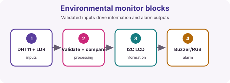
Inputs are temperature, humidity and light. Processing validates readings and compares thresholds. Outputs are LCD information and visual/audible warnings.
Integration order
Test LCD, then DHT11, then LDR, then alarm. Combine only after each subsystem passes its own acceptance test.
Timing
DHT updates every two seconds; display and alarm logic can run more often. Use millis so the interface remains responsive.
Assessment evidence
Submit block diagram, wiring diagram, commented sketch, test table at three conditions, fault record and demonstration checklist.
Wiring and safe build sequence
- DHT DATA -> D2
- LDR divider junction -> A0
- I2C LCD SDA/SCL -> A4/A5
- Buzzer -> D6
- All modules share GND
Worked sketch
Download .ino sketch#include <Wire.h>
#include <LiquidCrystal_I2C.h>
#include <DHT.h>
LiquidCrystal_I2C lcd(0x27, 16, 2);
DHT dht(2, DHT11);
unsigned long lastSample = 0;
void setup() {
lcd.init();
lcd.backlight();
dht.begin();
pinMode(6, OUTPUT);
}
void loop() {
if (millis() - lastSample >= 2000) {
lastSample = millis();
float t = dht.readTemperature();
float h = dht.readHumidity();
int light = analogRead(A0);
lcd.setCursor(0, 0);
if (isnan(t) || isnan(h)) {
lcd.print("Sensor error ");
noTone(6);
return;
}
lcd.print("T:");
lcd.print(t, 1);
lcd.print("C H:");
lcd.print(h, 0);
lcd.print("% ");
lcd.setCursor(0, 1);
lcd.print("Light:");
lcd.print(light);
lcd.print(" ");
if (t >= 30.0) tone(6, 1000); else noTone(6);
}
}How the code works
- Subsystems use non-conflicting pins.
- Failed sensor data produces a clear error and safe alarm state.
- Trailing spaces keep both LCD rows clean.
Test and record evidence
Practical evidence checklist
Common faults and checks
- Retest each subsystem separately.
- Use I2C scanner and DHT failure messages.
- Check the buzzer type and pin.
Check your understanding
Q1. Why integrate one subsystem at a time?
Show answer
It localises faults and confirms each interface independently.
Q2. What evidence proves calibration?
Show answer
Recorded inputs/conditions, readings, chosen threshold and observed output.