
26. Capstone 2: Clock, Alarm & Servo
Build a timed actuator system without blocking delays.
Learning outcomes
- Share I2C between RTC and LCD
- Compare RTC time to an alarm setting
- Drive a servo and buzzer safely
- Implement alarm states and acknowledgment
Parts and preparation
Uno, DS1307 RTC, I2C LCD, servo with external supply, buzzer and button. Install the same libraries as lessons 13, 17 and 19.
Before power: inspect wiring, confirm supply voltage and ensure all connected circuits share GND.
Libraries for this lesson
In Arduino IDE 2 open Tools → Manage Libraries…. Search by the Library Manager name and install the package by the exact author below. Similar names from other authors can use different APIs and will break the example.
| Include | Library Manager name | Author | Install note |
|---|---|---|---|
Wire.h | Wire | Arduino | Built into the Arduino core. No Library Manager install required. |
RTClib.h | RTClib | Adafruit | Same package as lesson 19. Install via Library Manager. |
Servo.h | Servo | Arduino | Built-in with Arduino AVR Boards. No Library Manager install required. |
LiquidCrystal_I2C.h | LiquidCrystal I2C | Frank de Brabander | Needed if you add the I2C LCD display. Same package as lesson 17. |
Shared bus
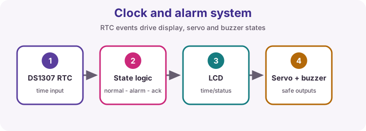
The RTC and LCD coexist on SDA/SCL because their I2C addresses differ.
State design
Normal, alarming and acknowledged states make behavior explicit. The button changes state; time and timers update outputs.
Actuator safety
Servo power is separate and grounds are common. The mechanism must not bind at end positions.
Acceptance test
Verify display time, trigger time, buzzer, servo movement, acknowledge button and power-cycle clock retention.
Wiring and safe build sequence
- RTC and LCD share A4/SDA, A5/SCL, 5 V and GND
- Servo signal -> D9; servo external supply GND -> Uno GND
- Buzzer -> D6
- Acknowledge button D2 -> GND with INPUT_PULLUP
Worked sketch
Download .ino sketch#include <Wire.h>
#include <RTClib.h>
#include <Servo.h>
RTC_DS1307 rtc;
Servo latch;
bool acknowledged = false;
void setup() {
rtc.begin();
latch.attach(9);
pinMode(2, INPUT_PULLUP);
pinMode(6, OUTPUT);
}
void loop() {
DateTime now = rtc.now();
bool alarmTime = now.hour() == 8 && now.minute() == 0;
if (digitalRead(2) == LOW) acknowledged = true;
if (!alarmTime) acknowledged = false;
if (alarmTime && !acknowledged) {
latch.write(90);
tone(6, 1200);
} else {
latch.write(10);
noTone(6);
}
}How the code works
- The example focuses on alarm state; add the LCD output from lesson 19.
- Acknowledgment resets after the alarm minute ends.
Test and record evidence
Practical evidence checklist
Common faults and checks
- Test with an alarm a minute ahead.
- Confirm the RTC was set and retains time.
- Power the servo separately.
Check your understanding
Q1. Why can RTC and LCD share I2C wires?
Show answer
They have different bus addresses.
Q2. What is the purpose of an acknowledged state?
Show answer
It records that the user silenced the current alarm event.