
30. College Practical Assessments
Demonstrate planning, construction, coding, testing and fault-finding.
Learning outcomes
- Interpret a practical brief
- Plan pin use and power before building
- Write and test modular code
- Present portfolio evidence and explain decisions
Parts and preparation
Uno starter kit, multimeter, practical logbook and assessment brief.
Before power: inspect wiring, confirm supply voltage and ensure all connected circuits share GND.
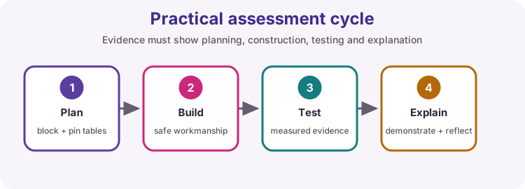
Assessment workflow
Read the full brief; identify inputs, outputs, constraints and success criteria; draw a block diagram; prepare a pin table and power budget; build/test modules; integrate; verify every criterion.
Practical Task A
Two-button controller: debounced inputs select three LED/PWM states and Serial reports state changes. Include a truth table and code explanation.
Practical Task B
Sensor alarm: read a chosen analogue sensor, display calibrated value, drive an alarm through safe hardware and use hysteresis.
Practical Task C
Integrated system: combine an I2C display, one digital sensor, one analogue sensor and one actuator using non-blocking timing.
Suggested rubric
Planning 15%; safe wiring/workmanship 20%; functional code 25%; measurements/testing 20%; fault-finding 10%; explanation and portfolio 10%.
Wiring and safe build sequence
- Submit a labelled circuit or connection diagram before energising
- Show power source, common ground and driver components
- Instructor/peer checks for shorts before first power
Worked sketch
Download .ino sketch// Code-correction exercise: identify and repair every fault.
const byte inputPin = 2;
const byte outputPin = 13;
void setup() {
pinMode(inputPin, INPUT_PULLUP);
pinMode(outputPin, OUTPUT);
}
void loop() {
bool pressed = digitalRead(inputPin) == LOW;
if (pressed) {
digitalWrite(outputPin, HIGH);
} else {
digitalWrite(outputPin, LOW);
}
}How the code works
- The downloadable file is the corrected reference. The assessment should first present a deliberately faulty version supplied by the lecturer.
- Learners must explain capitalization, pin modes, comparison, braces and semicolons.
Test and record evidence
Practical evidence checklist
Common faults and checks
- Return to the block diagram and test one subsystem.
- Use compiler messages and measured voltages rather than random rewiring.
Check your understanding
Q1. What should be produced before wiring?
Show answer
A block diagram, pin plan, power plan and connection diagram.
Q2. What demonstrates testing?
Show answer
A table of conditions, expected values, measured values and pass/fail results.