
10. Analogue Inputs, ADC & Voltage Dividers
Understand analogue versus digital signals, measure voltage with the Uno ADC, and scale readings into engineering values.
Learning outcomes
- Explain the difference between analogue and digital signals
- Explain 10-bit ADC resolution on a 5 V Uno
- Wire a potentiometer as a voltage divider into A0
- Convert ADC counts to volts and use map / constrain appropriately
Parts and preparation
Uno, 10 k ohm potentiometer, breadboard, jumper wires and multimeter.
Before power: inspect wiring, confirm supply voltage and ensure all connected circuits share GND.
Analogue vs digital signals
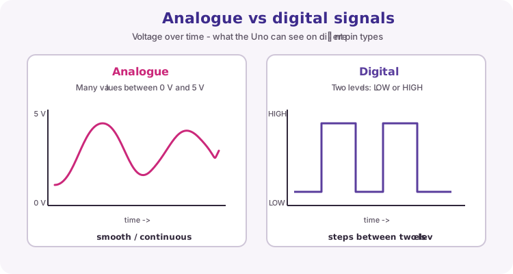
A digital signal (on digital pins) is treated as one of two logic levels: LOW (about 0 V) or HIGH (about 5 V on a Uno). Buttons, LEDs and most logic wires use this idea.
An analogue signal can sit at many voltages between those extremes - for example 1.2 V, 2.7 V or 4.1 V. Sensors such as potentiometers, LDRs and thermistor dividers produce analogue voltages. The Uno cannot store a true continuous voltage in a variable; it must convert it to a number first.
| Feature | Analogue | Digital |
|---|---|---|
| Voltage | Many values in a range (e.g. 0-5 V) | Two useful levels: LOW or HIGH |
| Typical use | Pots, light/temperature dividers | Buttons, LEDs, logic lines |
| Uno function | analogRead on A0-A5 | digitalRead / digitalWrite on D pins |
| Result in code | Integer code 0-1023 (after ADC) | LOW or HIGH (0 or 1 in practice) |
Where each type fits on the Uno
Digital pins D0-D13 are for digitalRead and digitalWrite (and PWM on pins marked ~). They are not meant for measuring a smoothly varying 0-5 V sensor voltage.
Analogue input pins A0-A5 connect to the ADC (analogue-to-digital converter). This lesson reads a potentiometer wiper on A0.

What the ADC does
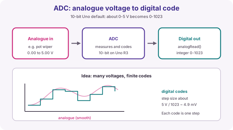
The ADC samples the voltage on an analogue pin and maps it to a whole-number code. On a classic Uno with the default 5 V reference, that code is 0 to 1023 (10-bit ADC: 2^10 = 1024 codes).
Roughly: 0 means near 0 V, 1023 means near 5 V. One step is about 5 / 1023 ≈ 4.89 mV. The continuous voltage is approximated by the nearest code - that is called quantisation.
| Item | Typical Uno R3 default |
|---|---|
| Reference | About 0-5 V (Vref = board 5 V rail) |
| Resolution | 10-bit (codes 0-1023) |
| Step size | About 4.9 mV per count |
| Function | analogRead(pin) |
Voltage divider and the potentiometer
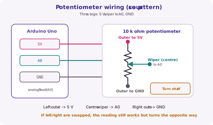
Two resistances in series across a supply share the voltage. A potentiometer is an adjustable divider: the wiper voltage sits between the two outer legs.
Course wiring: one outer leg to 5 V, the other to GND, wiper to A0. Turning the shaft changes the divider ratio, so analogRead changes.
Scaling counts to volts and percent
Voltage ≈ raw * Vref / 1023.0. Use 5.0 (with a decimal) so the division is floating-point, not integer.
map(raw, 0, 1023, 0, 100) is a convenient integer scale to percent. constrain(value, low, high) clips a number into a safe range. map does not protect against out-of-range inputs by itself.
int raw = analogRead(A0);
float voltage = raw * (5.0 / 1023.0);
int percent = map(raw, 0, 1023, 0, 100);
Measurement uncertainty
USB 5 V is not a perfect laboratory reference. For better accuracy, measure the actual 5 V rail with a multimeter and use that value as Vref in the formula. Average several readings if noise is visible on Serial.
Wiring and safe build sequence
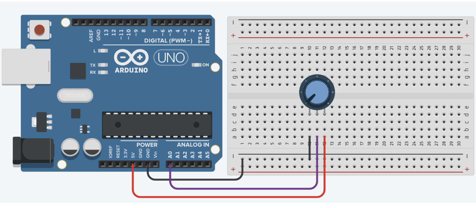
- Pot outer leg -> 5 V
- Other outer leg -> GND
- Centre wiper -> A0
Worked sketch
Download .ino sketchconst byte sensorPin = A0;
void setup() {
Serial.begin(9600);
}
void loop() {
int raw = analogRead(sensorPin);
float voltage = raw * (5.0 / 1023.0);
int percent = map(raw, 0, 1023, 0, 100);
Serial.print("ADC=");
Serial.print(raw);
Serial.print(" V=");
Serial.print(voltage, 2);
Serial.print(" %=");
Serial.println(percent);
delay(200);
}How the code works
- analogRead returns a digital code for an analogue voltage on A0.
- 5.0 forces floating-point calculation for voltage.
- The ADC count and voltage should rise together as the wiper moves toward 5 V.
Test and record evidence
Practical evidence checklist
Common faults and checks
- A fixed reading suggests the wiper is not connected to A0.
- Erratic readings can indicate a missing GND or poor breadboard contact.
- If voltage looks wrong, check that the outer legs really go to 5 V and GND.
Check your understanding
Q1. What is the main difference between an analogue and a digital signal on the Uno?
Show answer
Analogue can take many voltages in a range; digital is treated as LOW or HIGH.
Q2. How many codes does a 10-bit ADC have?
Show answer
1024 codes, numbered 0-1023.
Q3. Why use 5.0 instead of 5 in the voltage formula?
Show answer
To request floating-point division rather than integer arithmetic.
Q4. Which pins use analogRead for a voltage measurement?
Show answer
Analogue inputs A0-A5.
Optional: AREF with an LM4040 4.096 V reference
The main lesson uses the board 5 V rail as the ADC reference. That is fine for learning. USB 5 V can drift a little, so voltage estimates are only as stable as that rail.
An optional upgrade is an external precision shunt reference on the AREF pin. A common choice is the LM4040 (4.096 V). With that Vref, one ADC step is 4.096 / 1023 ≈ 4.00 mV, which makes mental maths neat, and the reference is far more stable than USB 5 V.
Skip this section on your first pass. Come back only when you want better absolute voltage accuracy.
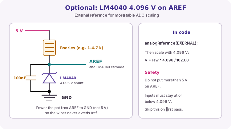
How the LM4040 is wired
The LM4040 is a shunt reference: it sits from the AREF node down to GND and holds about 4.096 V when a small bias current flows through a series resistor from 5 V.
Typical parts: LM4040-N 4.096 V (check your package pinout), series resistor about 1 k to 4.7 k ohm (enough current for the chip datasheet, but not wasteful), and shared GND with the Uno.
Power any divider you measure (for example the potentiometer) from AREF to GND, not from 5 V. If the pot still ran from 5 V, the wiper could go above 4.096 V and the ADC reading would saturate or be meaningless.
| Item | Value / note |
|---|---|
| Vref | 4.096 V (LM4040) |
| Step size | About 4.00 mV per ADC count |
| Code | analogReference(EXTERNAL); in setup |
| Scale | voltage = raw * (4.096 / 1023.0) |
| Sensor supply | From AREF to GND, not from 5 V |
- LM4040 anode -> GND (shared with Uno)
- LM4040 cathode -> AREF
- 5 V -> series resistor (e.g. 1-4.7 k ohm) -> AREF / LM4040 cathode
- Pot outer leg -> AREF (not 5 V)
- Other pot outer leg -> GND
- Pot wiper -> A0
Code change and safety rules
Call analogReference(EXTERNAL) once in setup() before any analogRead. Then use 4.096 in the voltage formula instead of 5.0.
Safety: never put more than 5 V on AREF. Keep every analogue input at or below the external reference (here 4.096 V). Do not leave an external voltage on AREF while the sketch still uses the default 5 V reference - set EXTERNAL first, or disconnect AREF when you are not using it.
If anything looks wrong, remove the AREF wiring, switch back to the default lesson setup, and confirm the pot still works with the normal 5 V formula before retrying the reference.
const byte sensorPin = A0;
const float VREF = 4.096;  // LM4040 on AREF

void setup() {
  analogReference(EXTERNAL);  // must match wiring on AREF
  Serial.begin(9600);
}

void loop() {
  int raw = analogRead(sensorPin);
  float voltage = raw * (VREF / 1023.0);
  Serial.print("ADC=");
  Serial.print(raw);
  Serial.print("  V=");
  Serial.println(voltage, 3);
  delay(200);
}