
23. UART, I2C & SPI Reference
Choose and troubleshoot common embedded communication buses.
Learning outcomes
- Compare UART, I2C and SPI by wiring, speed and how devices are selected
- Identify Uno hardware pins for UART, I2C and SPI
- Explain I2C addresses and SPI chip-select
- Choose a suitable bus for GPS, RTC and SD-style modules
- Run an I2C address scan with Wire
Parts and preparation
Arduino Uno and any I2C and/or SPI modules available in the kit (optional for the scan demo).
Before power: inspect wiring, confirm supply voltage and ensure all connected circuits share GND.
Libraries for this lesson
In Arduino IDE 2 open Tools → Manage Libraries…. Search by the Library Manager name and install the package by the exact author below. Similar names from other authors can use different APIs and will break the example.
| Include | Library Manager name | Author | Install note |
|---|---|---|---|
Wire.h | Wire | Arduino | Built into the Arduino core. No Library Manager install required. |
SPI.h | SPI | Arduino | Built into the Arduino core. Used later with SD / RFID modules; not required for the I2C scanner sketch. |
Three buses at a glance
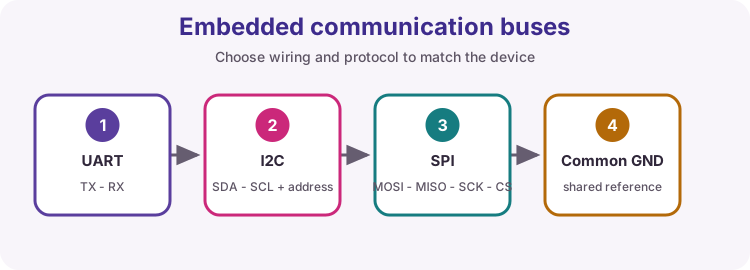
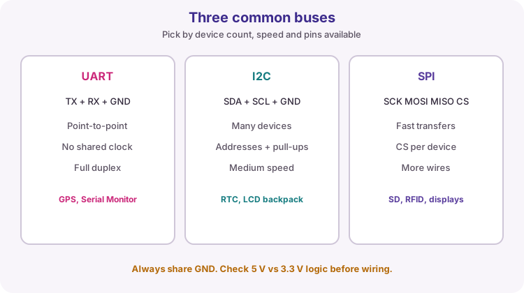
UART, I2C and SPI are the three buses you will meet most often in this course. They all need a common GND and matching logic voltage. They differ in how many devices share the wires, whether a clock line is shared, and how a device is selected.
This lesson is a reference: use it when wiring an unfamiliar module or when a project needs more than one device on the Uno.
| Bus | Signal wires (typical) | How devices are chosen |
|---|---|---|
| UART | TX, RX (+ GND) | Usually one partner per UART |
| I2C | SDA, SCL (+ GND) | 7-bit address on the shared bus |
| SPI | SCK, MOSI, MISO, CS (+ GND) | Chip-select pin per device |
UART
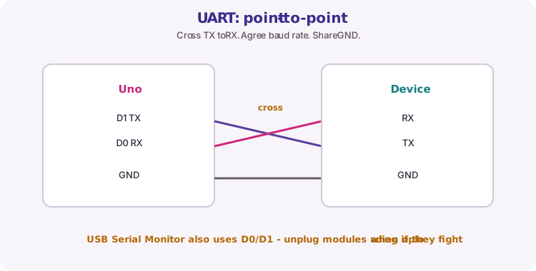
UART is asynchronous: both ends agree a baud rate (for example 9600) and send bytes without a shared clock wire. Wire TX of one device to RX of the other, RX to TX, and share GND. That crossover is easy to get wrong once.
On the Uno, hardware UART is D0 (RX) and D1 (TX). The USB Serial Monitor uses the same UART through the board USB bridge, so a GPS or other module on D0/D1 can block uploads or garble Serial output. SoftwareSerial on other pins is possible later; start by knowing D0/D1 are special.
I2C
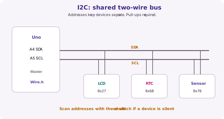
I2C is a two-wire shared bus: SDA carries data and SCL carries the clock. Several devices can share those wires because each has an address (for example LCD 0x27, RTC 0x68). Pull-up resistors hold idle lines HIGH; most modules include them (lesson 17).
On the Uno, SDA is A4 and SCL is A5. Use Wire.h. If a device stays silent, run the I2C scanner in this lesson before rewriting application code.
SPI
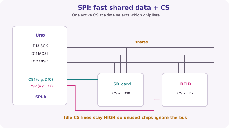
SPI is clocked and usually faster than I2C for bulk data. SCK is the clock, MOSI carries controller-to-device data, MISO returns device-to-controller data. Each device normally needs its own CS (chip select) pin. Only one CS is active (usually LOW) at a time; idle CS lines stay HIGH.
On the Uno, hardware SPI is D13 (SCK), D11 (MOSI), D12 (MISO). D10 is often used as SS / CS for the first device and also appears on the ICSP header. SD cards and RFID modules in later lessons use this pattern.
Uno pin map
Memorize the hardware pins for this course. They are fixed on the Uno R3 - swapping them casually usually means you are no longer using the hardware peripheral.
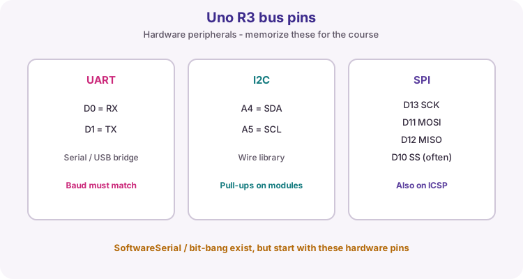
| Bus | Uno R3 pins |
|---|---|
| UART | D0 RX, D1 TX |
| I2C | A4 SDA, A5 SCL |
| SPI | D13 SCK, D11 MOSI, D12 MISO, CS as chosen (often D10) |
| SPI alt | Same SPI signals on the ICSP header |
Choosing a bus
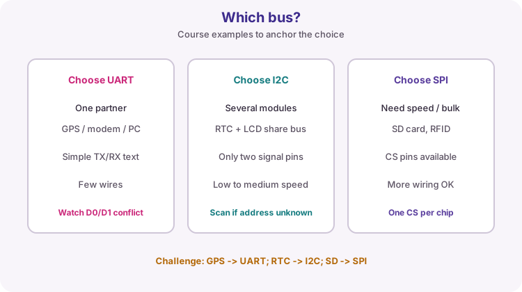
Match the module datasheet first - you rarely get to invent the bus. When you do choose: UART for one serial partner (GPS, PC text), I2C when several sensors/displays must share two wires, SPI when you need speed or the part is SPI-only (SD, many RFID readers).
Voltage matters: a 3.3 V SPI flash or sensor may not tolerate 5 V Uno pins. Always check logic levels before connecting.
I2C scanner sketch
The worked sketch walks every 7-bit address and prints those that acknowledge. Wire.begin() starts the bus as master. endTransmission() returning 0 means a device answered at that address.
Wire.beginTransmission(address);
if (Wire.endTransmission() == 0) {
  // device present at address
}
Wiring and safe build sequence
- Always connect common GND
- Check module logic voltage before connection
- Keep bus wires short in breadboard prototypes
- Do not assume every module is 5 V tolerant
- I2C scan demo: module VCC/GND/SDA/SCL to Uno 5 V (if rated), GND, A4, A5
Worked sketch
Download .ino sketch#include <Wire.h>
void setup() {
Serial.begin(9600);
Wire.begin();
Serial.println("I2C addresses:");
for (byte address = 1; address < 127; address++) {
Wire.beginTransmission(address);
if (Wire.endTransmission() == 0) {
Serial.print("0x");
if (address < 16) Serial.print('0');
Serial.println(address, HEX);
}
}
}
void loop() {}How the code works
- The scanner attempts every valid 7-bit address once in setup.
- A zero return from endTransmission indicates an acknowledged address.
- No printed addresses usually means wiring, power, pull-ups or voltage mismatch.
Test and record evidence
Practical evidence checklist
Common faults and checks
- No addresses: check power, GND, SDA/SCL swapped, and pull-ups.
- Several unexpected addresses may indicate noise or voltage problems.
- UART upload fails: disconnect anything wired to D0/D1, then try again.
- SPI device silent: confirm CS pin, idle HIGH on unused CS lines, and shared GND.
- Confirm 5 V vs 3.3 V module ratings before powering.
Check your understanding
Q1. Which bus uses a chip-select line per device?
Show answer
SPI.
Q2. Which bus uses device addresses on two shared wires?
Show answer
I2C.
Q3. Which Uno pins are hardware UART?
Show answer
D0 (RX) and D1 (TX).
Q4. Why cross TX to RX on UART?
Show answer
Each side transmits on TX and listens on RX - they must meet.