
20. Thermistors, LDRs & Calibration
Understand how NTC thermistors and LDRs change resistance, wire them as voltage dividers, convert ADC counts to resistance and temperature, and calibrate thresholds with hysteresis.
Learning outcomes
- Explain how an NTC thermistor and an LDR change resistance with temperature and light
- Wire a resistive sensor with a fixed resistor as a voltage divider into an analogue pin
- Calculate sensor resistance from an ADC reading for the course wiring order
- Convert an NTC resistance to Celsius using the Beta equation
- Calibrate ON/OFF thresholds with hysteresis to prevent output chatter
Parts and preparation
Uno, 10 kΩ NTC thermistor, 10 kΩ fixed resistor(s), LDR, breadboard, jumper wires. Optional: LEDs or the MOSFET fan driver from lesson 12 for a threshold demo.
Before power: inspect wiring, confirm supply voltage and ensure all connected circuits share GND.
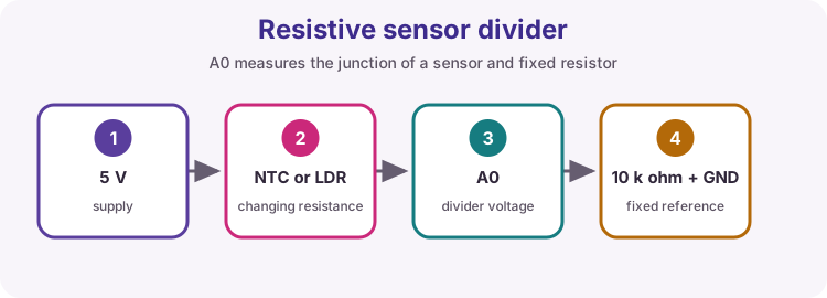
Why resistive sensors need a voltage divider
Arduino analogue pins measure voltage (0 to about 5 V on an Uno), not resistance. An NTC thermistor or LDR only changes resistance as the environment changes. To turn that into a readable voltage, place the sensor in series with a known fixed resistor. The mid-point voltage is a fraction of the supply. That mid-point goes to A0 (or A1).
This is the same divider idea as the potentiometer in lesson 10, except one resistance is fixed and the other is the sensor.
| What changes | What Arduino measures | What you calculate |
|---|---|---|
| Sensor resistance (ohms) | ADC count 0-1023 (voltage) | Resistance, then temperature or light threshold |
| Wiring order and Rfixed | Direction of the reading | Which formula to use |
How an NTC thermistor works
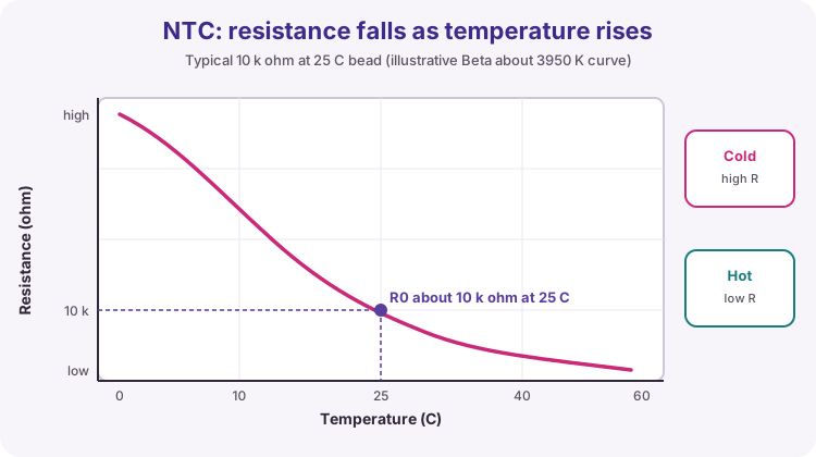
A thermistor is a resistor whose resistance depends strongly on temperature. NTC means Negative Temperature Coefficient: as temperature rises, resistance falls.
Inside a typical bead NTC, a metal-oxide semiconductor material changes how easily charge carriers move. Warmer material usually conducts better, so resistance drops. Classroom kits often use a 10 kΩ NTC: about 10 kΩ at 25 °C (298.15 K), with a datasheet Beta (B) value often near 3950 K.
PTC thermistors (Positive Temperature Coefficient) do the opposite and are less common in this course. Always check the marking or datasheet: wrong type or wrong R0 ruins the Beta maths.
| Term | Meaning |
|---|---|
| NTC | Resistance falls when temperature rises |
| R0 | Nominal resistance at reference temperature T0 (often 10 kΩ at 25 °C) |
| Beta (B) | Datasheet constant (kelvin) used in the simple temperature equation |
| Self-heating | Too much current through the NTC warms it and skews the reading - keep divider current modest |
How an LDR works
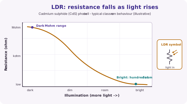
An LDR (Light Dependent Resistor), often a cadmium sulphide (CdS) cell, changes resistance with illumination. In the dark, resistance can be megaohms. In bright light it may fall to a few hundred ohms.
Light frees charge carriers in the photoconductive material, so conductivity rises and resistance falls. LDRs are slow compared with photodiodes (often tens to hundreds of milliseconds) and are nonlinear, so this course usually uses them for thresholds (dark / bright) rather than calibrated lux.
Wire an LDR the same way as the NTC: 10 kΩ pull-up to 5 V, LDR to GND, junction into A1. Choose Rfixed near the LDR resistance in the light level you care about so the ADC uses more of its range.
| Condition | Typical LDR resistance (order of magnitude) |
|---|---|
| Dark / covered | Hundreds of kΩ to MΩ |
| Indoor room light | Often low kΩ range (part-dependent) |
| Bright / near a lamp | Hundreds of ohms |
Divider calculation (course wiring)
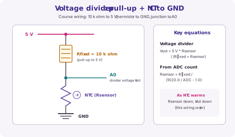
Course wiring uses a fixed pull-up to 5 V and the sensor to GND (same order as the SimpleThermistor library in lesson 33):
5 V → 10 kΩ pull-up → junction to A0 → NTC (or LDR) → GND
Voltage at the junction: Vout = 5 V × Rsensor / (Rfixed + Rsensor).
The Uno ADC maps about 0-5 V to 0-1023. From the ADC count you can recover resistance:
Rsensor = Rfixed / (1023.0 / ADC - 1.0)
Equivalently: Rsensor = Rfixed × ADC / (1023.0 - ADC).
If you swap sensor and fixed resistor, both the voltage direction and this formula change. Always match the code to the physical order.
| ADC reading | Rough meaning (this wiring, 10 kΩ pull-up) |
|---|---|
| Near 0 | Junction near GND - shorted sensor, open pull-up, or very low Rsensor |
| Near 512 | Rsensor ≈ Rfixed (about equal share of 5 V) |
| Near 1023 | Junction near 5 V - open sensor / broken GND side, or very high Rsensor |
Worked resistance example
Suppose Rfixed = 10000 Ω and analogRead returns 512.
Rsensor = 10000 / (1023.0 / 512 - 1.0) ≈ 10000 / (2.00 - 1.0) ≈ 10000 Ω.
So the sensor is about equal to the pull-up - for a 10 kΩ NTC that is near room temperature if R0 is 10 kΩ at 25 °C (exact Celsius still needs the Beta step).
If ADC = 0 or 1023, do not trust the formula: you risk division by zero or a meaningless result. The worked sketch treats those as a divider fault.
Beta equation: resistance to temperature
The Beta model converts NTC resistance to absolute temperature in kelvin:
1/T = 1/T0 + ln(R / R0) / B
T and T0 are in kelvin. T0 is usually 25 °C → 25 + 273.15 = 298.15 K. R0 is the resistance at T0. B is the datasheet Beta constant.
Then Celsius = T - 273.15.
Use float maths and the C log() natural logarithm from math.h. Wrong B or R0 values produce smoothly wrong temperatures - always copy constants from your part datasheet.
| Symbol | Typical course value | Notes |
|---|---|---|
| R0 | 10000 Ω | At T0; confirm on your NTC |
| T0 | 298.15 K (25 °C) | Must match the temperature used for R0 |
| B | Often ~3950 K | Datasheet Beta; varies by part |
| R | From divider formula | Must use the same wiring as the formula |
#include <math.h>

const float seriesR = 10000.0;      // Rfixed pull-up
const float nominalR = 10000.0;     // R0 at T0
const float nominalK = 25.0 + 273.15;
const float beta = 3950.0;          // B from datasheet

float resistance = seriesR / (1023.0 / raw - 1.0);
float invT = 1.0 / nominalK + log(resistance / nominalR) / beta;
float celsius = 1.0 / invT - 273.15;
Calibration and hysteresis
Real parts have tolerance. Breadboard contact resistance, supply voltage and self-heating add error. Calibrate against a known reference (room thermometer, ice-water bath for ~0 °C, covered vs open LDR) and record ADC or Celsius values in your logbook.
For on/off control (fan, lamp, alarm), do not use a single threshold. Noise around that point makes the output chatter. Use hysteresis: turn ON above one value and OFF only below a lower value (or the reverse for a heater / night light).
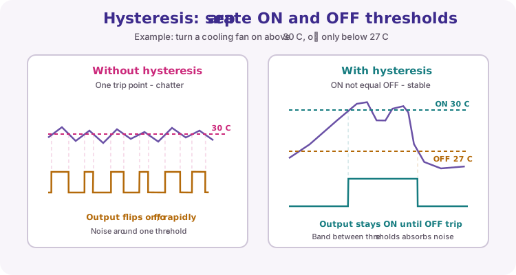
const float onC = 30.0;
const float offC = 27.0;
bool fanOn = false;

if (!fanOn && celsius >= onC) {
  fanOn = true;   // rising trip
} else if (fanOn && celsius <= offC) {
  fanOn = false;  // falling trip
}
// Drive MOSFET/fan from lesson 12 using fanOn - never from an Uno pin directly
LDR thresholds (no Beta equation)
LDRs do not use the NTC Beta equation. For light control, read the divider ADC (or compute resistance) and set ON/OFF thresholds by experiment: cover the LDR, note the reading; uncover it under room light; pick values between those two with hysteresis.
If you need true lux, use a digital light sensor later - the LDR path in this lesson is for reliable dark/bright decisions.
Your own library
Once the thermistor maths works in a sketch, package it as a reusable library with a .h header and .cpp source file in Documents/Arduino/libraries/. See the course extension: How to create a SimpleThermistor library.
Wiring and safe build sequence
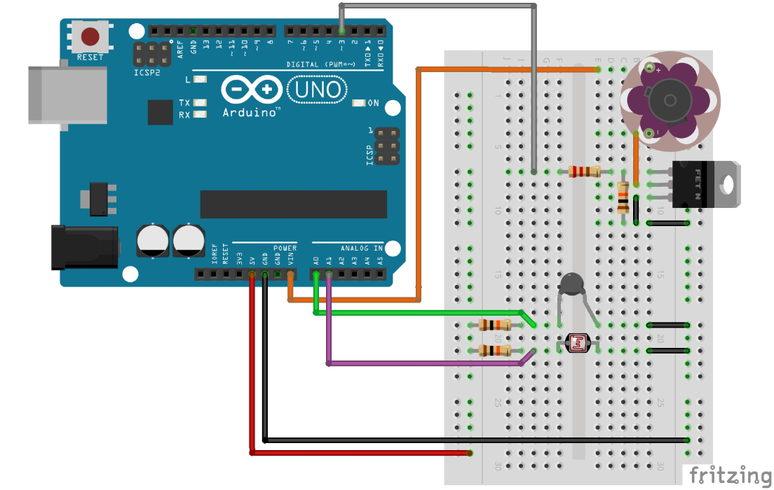
- 5 V -> 10 kΩ pull-up -> A0 junction -> NTC -> GND
- Use a separate similar divider on A1 for the LDR (pull-up to 5 V, LDR to GND)
- Drive any fan through the MOSFET circuit from lesson 12 (not directly from an I/O pin)
Worked sketch 1: Thermistor on A0
Download .ino sketch#include <math.h>
const float seriesR = 10000.0;
const float nominalR = 10000.0;
const float nominalK = 25.0 + 273.15;
const float beta = 3950.0;
void setup() {
Serial.begin(9600);
}
void loop() {
int raw = analogRead(A0);
if (raw <= 0 || raw >= 1023) {
Serial.println("Divider fault");
delay(500);
return;
}
float resistance = seriesR / (1023.0 / raw - 1.0);
float invT = 1.0 / nominalK + log(resistance / nominalR) / beta;
float celsius = 1.0 / invT - 273.15;
Serial.print(celsius, 1);
Serial.println(" C");
delay(500);
}How the code works
- Reads only the thermistor divider on A0.
- The formula assumes 10 kΩ pull-up to 5 V and thermistor to GND (course wiring / SimpleThermistor).
- Boundary checks avoid division by zero and flag open/short wiring.
- Use datasheet R0 and Beta values for your actual thermistor.
- Serial.print(celsius, 1) shows one decimal place.
Worked sketch 2: LDR on A1
Download .ino sketchWhat this sketch is for: Same divider idea as the thermistor, but on A1 for the LDR. Prints the raw ADC count and calculated resistance so you can choose dark/bright thresholds. No Beta temperature maths - LDRs are used for light level decisions, not calibrated lux.
const float seriesR = 10000.0;  // pull-up to 5 V

void setup() {
  Serial.begin(9600);
  Serial.println("LDR on A1 (pull-up to 5 V, LDR to GND)");
}

void loop() {
  int raw = analogRead(A1);
  if (raw <= 0 || raw >= 1023) {
    Serial.println("Divider fault");
    delay(500);
    return;
  }

  // Same divider order as the thermistor sketch: Rfixed to 5 V, sensor to GND
  float resistance = seriesR / (1023.0 / raw - 1.0);

  Serial.print("ADC ");
  Serial.print(raw);
  Serial.print("  R ");
  Serial.print(resistance, 0);
  Serial.println(" ohm");
  delay(500);
}
How the code works
- Reads only the LDR divider on A1 - separate from the thermistor sketch.
- Formula matches course wiring: 5 V -> 10 kΩ -> A1 -> LDR -> GND.
- Use the printed ADC values to pick ON/OFF thresholds with hysteresis.
- Boundary checks flag open/short wiring the same way as the thermistor sketch.
Test and record evidence
Practical evidence checklist
Common faults and checks
- If temperature moves backwards or is unrealistic, check divider order and the resistance formula.
- Confirm R0, T0 and Beta match the datasheet for your NTC.
- Do not heat a thermistor with a flame or high-power source - use body heat or warm air only.
- ADC stuck at 0 or 1023: check for open wires, swapped rails, or a short across the sensor/resistor.
- If the LDR sketch never changes, confirm the LDR divider is on A1 and matches pull-up to 5 V / LDR to GND.
Check your understanding
Q1. Why use a voltage divider with an NTC or LDR?
Show answer
The ADC measures voltage; the sensor only changes resistance.
Q2. What does NTC mean for resistance as temperature rises?
Show answer
Resistance falls (negative temperature coefficient).
Q3. For the course wiring (pull-up to 5 V, sensor to GND), what is Rsensor?
Show answer
Rsensor = Rfixed / (1023.0 / ADC - 1.0).
Q4. In the Beta equation, what units must T and T0 use?
Show answer
Kelvin.
Q5. What is hysteresis in an on/off control?
Show answer
Different switch-on and switch-off thresholds that prevent chatter.