
12. Transistors, MOSFETs & Relays
Switch loads safely without overloading an Arduino pin.
Learning outcomes
- Explain why loads need drivers
- Compare an NPN low-side switch with a logic-level N-MOSFET
- Wire a logic-level N-MOSFET low-side switch with gate resistors
- Place a flyback diode correctly across an inductive load
- Describe relay coil versus contacts and keep to ELV DC only
Parts and preparation
Uno, logic-level N-MOSFET, 220 ohm gate resistor, 10 k ohm gate pull-down, diode, low-voltage DC fan or lamp and external supply. Optional: NPN (e.g. 2N2222), base resistor and 5 V relay module for comparison.
Before power: inspect wiring, confirm supply voltage and ensure all connected circuits share GND.
Why loads need a driver
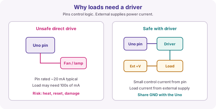
An Arduino Uno I/O pin is a logic control line, typically safe around 20 mA continuous. Fans, lamps, motors and relay coils often need far more current, and motors/relays are inductive.
A driver (NPN transistor, MOSFET, or a module) lets the pin switch a small control signal while an external supply provides the load current. Always join the external supply GND to the Uno GND so the control voltage has a common reference.
NPN transistor as a low-side switch
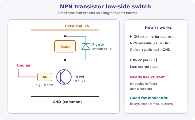
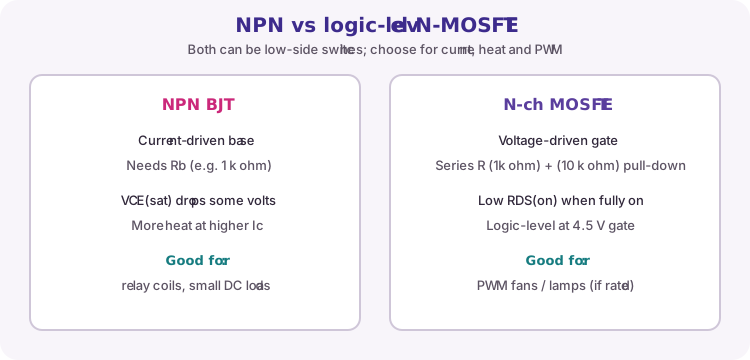
An NPN bipolar transistor can switch a load on the low side: load from external +V to the collector, emitter to GND. A base resistor (often about 1 k ohm) limits base current from the Arduino pin.
When the pin is HIGH, base current turns the NPN on and collector current flows through the load. When the pin is LOW, the transistor is off. NPNs are current-driven: you must budget base current (roughly collector current divided by beta, with a safety margin). They suit modest loads such as relay coils, buzzers and small lamps.
| Terminal | Connects to |
|---|---|
| Collector (C) | Load return (switched node) |
| Base (B) | Arduino pin via Rb |
| Emitter (E) | Common GND |
| Load + | External +V (not the Uno pin) |
Logic-level N-channel MOSFET
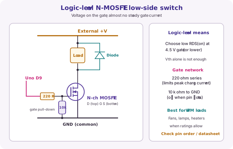
An N-channel enhancement MOSFET is also used as a low-side switch: load from +V to drain, source to GND. The gate is driven by voltage, so steady gate current is tiny compared with an NPN base.
Logic-level means the datasheet shows a useful low RDS(on) at about 4.5 V gate (or lower) - not merely that the threshold voltage Vth is under 5 V. A non-logic-level part may stay partly on, run hot, and fail.
Course gate network: series ~220 ohm from the pin to the gate (limits peak charge current), and ~10 k ohm from gate to GND (keeps the MOSFET off if the pin floats). This lesson's practical build uses the MOSFET with PWM on D9.
| Item | Course practice |
|---|---|
| Device | Logic-level N-ch MOSFET (check datasheet) |
| Series gate R | About 220 ohm |
| Gate pull-down | About 10 k ohm to GND |
| Control | digitalWrite or analogWrite (PWM) |
NPN vs N-MOSFET
Both can switch a load to GND. Prefer an NPN for simple modest DC loads and many relay-coil drivers. Prefer a logic-level N-MOSFET when you want efficient PWM into a fan or lamp and the part is rated for the current.
Always check package pin order - TO-92, TO-220 and SMD packages are not interchangeable by guesswork.
Suggested parts (South Africa)
These are practical examples often stocked by South African distributors such as Mantech Electronics (mantech.co.za). Search the part number on the site and always confirm the datasheet, pinout and current rating for your load. Stock changes - treat this as a shopping starting point, not a guarantee.
| Type | Package | Example part | Typical course use |
|---|---|---|---|
| NPN | SMD (SOT-23) | MMBT2222A / MMBT3904 | Small PCB loads, LED strips (check Ic) |
| NPN | TO-92 | BC337 / 2N2222A | Breadboard: relays, buzzers, small lamps |
| NPN power | TO-220 | TIP31C (or TIP120 Darlington) | Higher current DC switching (watch heat / VCE sat) |
| N-MOSFET logic | SMD (SOT-23) | 2N7002 | Small PWM / signal switching only |
| N-MOSFET logic | TO-92 | 2N7000 | Breadboard demos; low current loads |
| N-MOSFET logic power | TO-220 | IRLZ44N | Fans / lamps with PWM (course-style low-side) |
Flyback diode
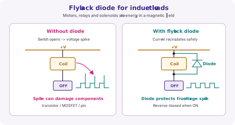
Inductive loads (motors, relay coils, solenoids) store energy in a magnetic field. When you switch the current off, that energy tries to keep the current flowing and can produce a high voltage spike that damages the transistor, MOSFET or nearby electronics.
Place a diode reverse-biased across the coil during normal on-state: cathode toward the positive supply, anode toward the switched (transistor/MOSFET) side. When the switch opens, the diode gives the current a safe path.
Relays and module limits
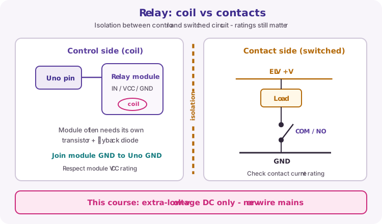
A relay uses a coil (inductive) to move mechanical contacts. The coil side and the contact side can be electrically isolated, which is useful for separating circuits - but contact voltage and current ratings still apply.
Many Arduino relay modules include their own driver transistor and flyback diode; you drive an IN pin and supply VCC/GND. This course switches only extra-low-voltage DC loads. Do not wire mains electricity. If you ever drive a bare relay coil from a discrete NPN, treat the coil as an inductive load with a flyback diode.
Wiring and safe build sequence
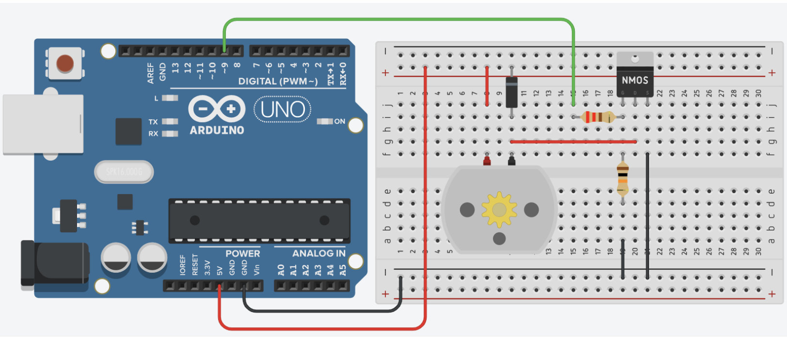
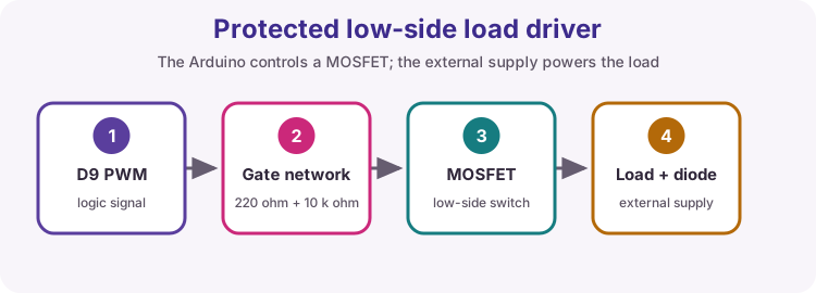
- D9 -> 220 ohm -> MOSFET gate
- 10 k ohm from gate -> GND
- MOSFET source -> common GND
- Load between external +V and drain
- Diode across inductive load (cathode to +V)
- External supply GND -> Uno GND
Worked sketch
Download .ino sketchconst byte loadPin = 9;
void setup() {
pinMode(loadPin, OUTPUT);
}
void loop() {
for (int power = 0; power <= 255; power++) {
analogWrite(loadPin, power);
delay(10);
}
analogWrite(loadPin, 0);
delay(1000);
}How the code works
- The Arduino drives only the gate; the external supply provides load current.
- PWM can control a DC fan or lamp when the driver and load support it.
- If you substitute an NPN for on/off tests, use digitalWrite and a suitable base resistor - do not assume the same PWM thermal behaviour.
Test and record evidence
Practical evidence checklist
Common faults and checks
- Confirm MOSFET pin order from its datasheet.
- A non-logic-level MOSFET may overheat at 5 V gate drive.
- Common GND is essential.
- Missing flyback diode on motors/relays can cause random resets or damaged drivers.
Check your understanding
Q1. Why not power a fan from an I/O pin?
Show answer
Its current and inductive behavior exceed the pin's safe capability.
Q2. What makes a MOSFET 'logic-level' for 5 V Arduino use?
Show answer
Useful low RDS(on) at about 4.5 V gate (or lower), not only a low Vth.
Q3. How is a flyback diode oriented?
Show answer
Reverse-biased during normal operation: cathode to positive, anode to the switched side.
Q4. What must you never switch with a course relay build?
Show answer
Mains electricity - use extra-low-voltage DC only.