
13. Servo Motors
Command and safely power a closed-loop position actuator.
Learning outcomes
- Describe the motor, gears, feedback pot and control board inside a hobby servo
- Explain closed-loop position control (command vs feedback)
- Relate pulse width (~1-2 ms in a ~20 ms frame) to requested angle
- Use Servo.h attach and write with a safe angle range
- Power the servo from a suitable external supply with common GND
Parts and preparation
Uno, small hobby servo, 10 k ohm potentiometer and regulated 5-6 V supply.
Before power: inspect wiring, confirm supply voltage and ensure all connected circuits share GND.
Libraries for this lesson
In Arduino IDE 2 open Tools → Manage Libraries…. Search by the Library Manager name and install the package by the exact author below. Similar names from other authors can use different APIs and will break the example.
| Include | Library Manager name | Author | Install note |
|---|---|---|---|
Servo.h | Servo | Arduino | Built-in with Arduino AVR Boards. No Library Manager install required. |
What a hobby servo is
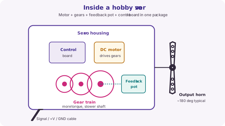
A hobby servo is a position actuator in a small package. Inside you typically find a DC motor, a reduction gear train, an output shaft with a horn, a feedback potentiometer linked to the shaft, and a control board.
The gears trade speed for torque so a small motor can hold useful loads. Most positional hobby servos travel about 180 degrees (exact travel varies). Continuous-rotation 'servos' are different: they use the same pulse interface for speed/direction, not angle.
Closed-loop position control
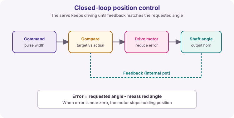
The Arduino does not force the shaft like an open-loop stepper step. It sends a position command. The servo compares that command with the feedback pot reading and drives the motor until the error is small.
If you push the horn by hand, the servo fights back toward the commanded angle (while powered). write() requests a position; it does not wait for, or prove, that the shaft has arrived.
Control signal: pulse width
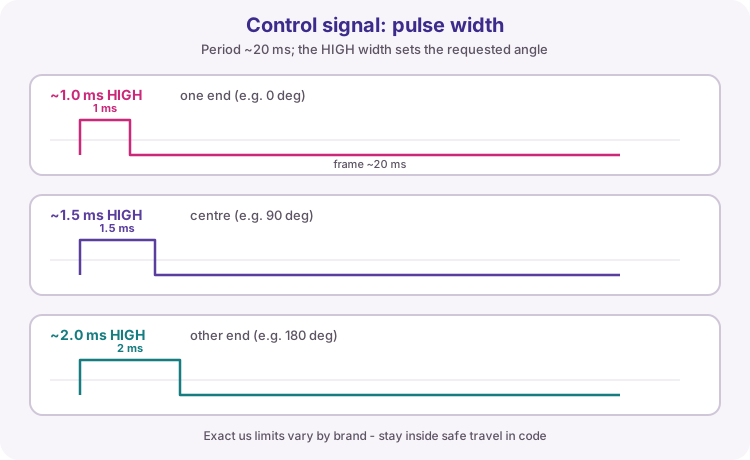
The signal wire carries a digital pulse train. Frames typically repeat about every 20 ms (50 Hz). The HIGH pulse width encodes the requested angle.
A common mapping is about 1.0 ms for one end, 1.5 ms for centre, and 2.0 ms for the other end. Real servos differ - some need slightly shorter or longer pulses at the ends. Driving past the mechanical stops can stall the motor, draw high current and strip gears.
| Typical pulse | Typical meaning |
|---|---|
| ~1.0 ms HIGH | One end of travel |
| ~1.5 ms HIGH | Centre |
| ~2.0 ms HIGH | Other end of travel |
| Frame ~20 ms | Pulse repeated regularly |
Servo.h and write(angle)
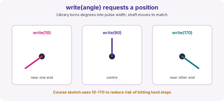
Servo.h generates the pulse train for you. arm.attach(9) starts pulses on D9. arm.write(angle) requests an angle in degrees; the library converts that to pulse width.
This lesson maps a potentiometer to a safe range such as 10-170 degrees so the horn is less likely to slam into hard stops. Calibrate limits for your specific servo if you need full travel.
#include <Servo.h>
Servo arm;
void setup() { arm.attach(9); }
void loop() {
  int angle = map(analogRead(A0), 0, 1023, 10, 170);
  arm.write(angle);
  delay(15);
}
Power and common ground
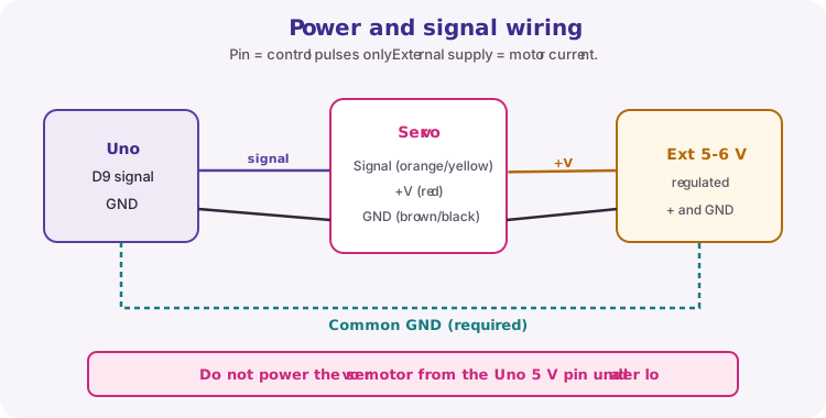
Servo current rises while moving and can jump sharply when stalled or heavily loaded. USB/Uno 5 V is often not enough and can cause brown-outs, resets and jitter.
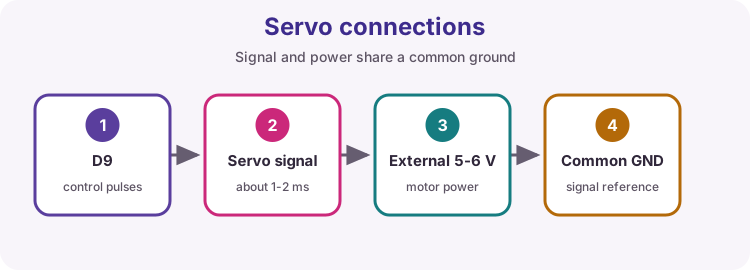
Use a regulated external 5-6 V supply sized for the servo (check its stall current). Connect servo red to that +V, brown/black to supply GND, signal to D9, and join supply GND to Uno GND so the pulse has a valid voltage reference.
Wiring and safe build sequence
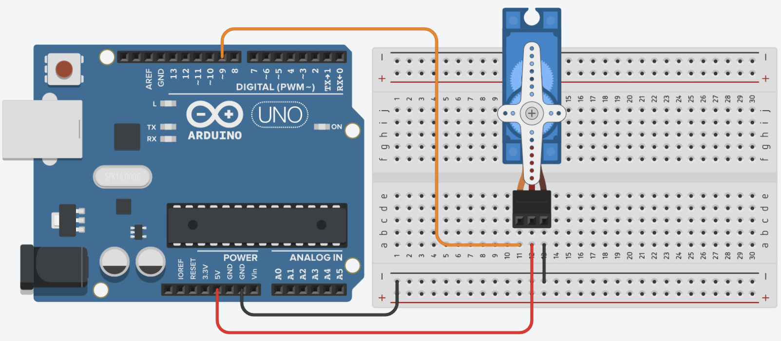
- Servo signal -> D9
- Servo red -> external regulated +5 V
- Servo brown/black -> external GND
- External GND -> Uno GND
- Pot wiper -> A0; outer legs -> 5 V/GND
Worked sketch
Download .ino sketch#include <Servo.h>
Servo arm;
void setup() {
arm.attach(9);
}
void loop() {
int raw = analogRead(A0);
int angle = map(raw, 0, 1023, 10, 170);
arm.write(angle);
delay(15);
}How the code works
- The 10-170 degree limits reduce the risk of driving against mechanical end stops.
- write requests a position; it does not confirm the shaft reached it.
- delay(15) gives the servo time to move between small updates without flooding the loop.
Test and record evidence
Practical evidence checklist
Common faults and checks
- Resetting or jitter usually indicates weak power or missing common GND.
- Disconnect the mechanical load while testing limits.
- If travel looks wrong, your servo's us endpoints may differ - stay inside a safe write range first.
Check your understanding
Q1. Why is a hobby servo called closed-loop?
Show answer
It compares the commanded position with internal feedback and drives the motor to reduce the error.
Q2. What mainly encodes the requested angle on the signal wire?
Show answer
The HIGH pulse width (about 1-2 ms) within a roughly 20 ms frame.
Q3. Why use external power?
Show answer
Movement and stall current can exceed the Uno regulator/USB capability.
Q4. Does write() prove the horn reached the angle?
Show answer
No - it requests a position; the servo tries to get there under its own control loop.