
22. Infrared Remote Control
Decode modulated infrared commands and map them to actions.
Learning outcomes
- Explain how a remote modulates IR light and a 38 kHz receiver demodulates it
- Wire an IR receiver safely after checking its pin labels
- Use IRremote 4.x (IRremote.hpp and IrReceiver) to print protocol and command
- Capture your own remote codes, then map commands to sketch actions
Parts and preparation
Uno, 38 kHz IR receiver module, compatible IR remote, jumper wires, and IRremote by shirriff / z3t0 / ArminJo (see Libraries box).
Before power: inspect wiring, confirm supply voltage and ensure all connected circuits share GND.
Libraries for this lesson
In Arduino IDE 2 open Tools → Manage Libraries…. Search by the Library Manager name and install the package by the exact author below. Similar names from other authors can use different APIs and will break the example.
| Include | Library Manager name | Author | Install note |
|---|---|---|---|
IRremote.hpp | IRremote | shirriff, z3t0, ArminJo | Install IRremote 4.x via Library Manager (maintainer Armin Joachimsmeyer). Older forks or 2.x examples use a different API. |
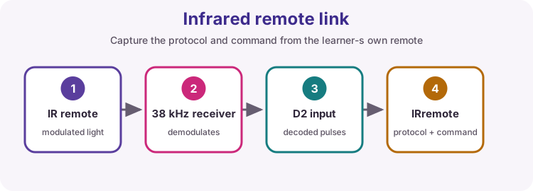
IR remote vs IR obstacle sensor
This lesson uses a demodulating IR receiver module made for TV-style remotes (often labelled VS1838B or similar), plus a handset that flashes an infrared LED.
It is not the same as a reflective IR proximity / obstacle pair (those measure reflected light for distance or detection). Here the remote encodes button presses as timed bursts of infrared light; the receiver turns that into digital pulses for the Uno.
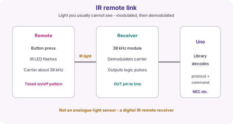
Carrier, demodulation and protocols
Most consumer remotes modulate a carrier near 38 kHz so ambient light is less likely to look like a button press. The module strips that carrier and leaves a pulse train the MCU can time.
Protocols such as NEC define how address and command bits are packed into those pulses. You do not need to bit-bang the timing for this course - IRremote does that - but you do need to capture the protocol and command your handset actually sends.
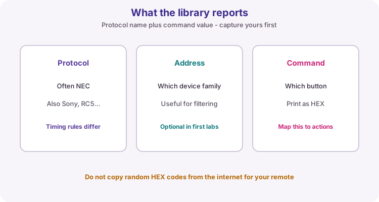
| Term | Meaning |
|---|---|
| Carrier | About 38 kHz IR on/off that the module expects |
| Protocol | Timing rules (often NEC on kit remotes) |
| Command | Value for which button was pressed |
| Repeat | Held button may send repeat frames - handle if needed |
Receiver pinout
Typical modules have three pins: VCC, GND and OUT (signal). Left-to-right order is not universal - some boards print OUT GND VCC, others VCC GND OUT. Always follow the silkscreen or datasheet before powering.
Course practice: OUT to D2, VCC to the voltage the module is rated for (commonly 5 V on Uno kits), GND shared. Aim the dome toward the remote and keep strong sunlight or some fluorescent lamps off the face if reception is noisy.
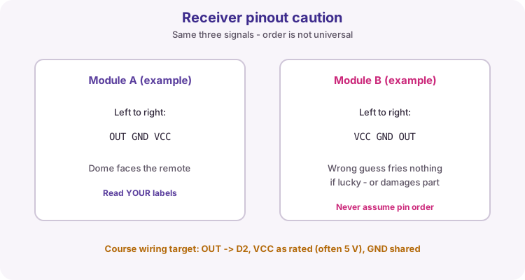
| Connection | Course practice |
|---|---|
| OUT | D2 |
| VCC | Module-rated supply (often 5 V) |
| GND | Uno GND |
| Remote | Point at the receiver dome |
IRremote 4.x API
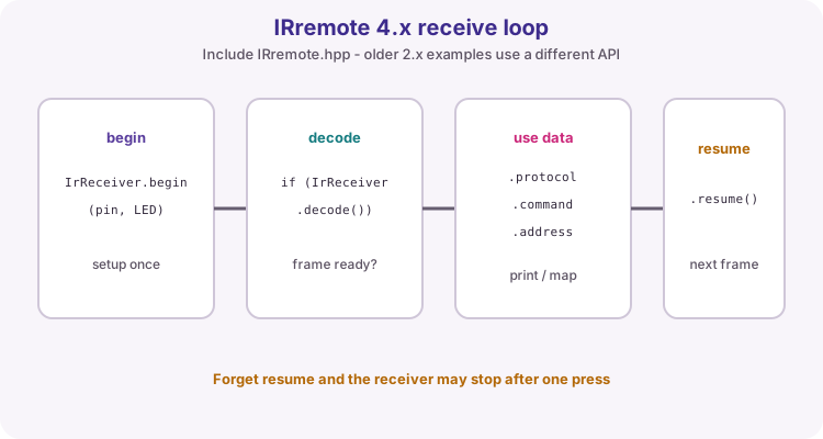
Install IRremote 4.x from Library Manager (shirriff / z3t0 / ArminJo). Include IRremote.hpp. Call IrReceiver.begin in setup with the receive pin and optional LED feedback. In loop, if IrReceiver.decode() is true, read IrReceiver.decodedIRData, then call IrReceiver.resume().
Older tutorials and IRremote 2.x use a different object and header. If an example will not compile, check the major version before rewriting everything.
#include <IRremote.hpp>
const byte receivePin = 2;

void setup() {
  Serial.begin(9600);
  IrReceiver.begin(receivePin, ENABLE_LED_FEEDBACK);
}

void loop() {
  if (IrReceiver.decode()) {
    Serial.print(getProtocolString(IrReceiver.decodedIRData.protocol));
    Serial.print(" 0x");
    Serial.println(IrReceiver.decodedIRData.command, HEX);
    IrReceiver.resume();
  }
}
Capture, then map
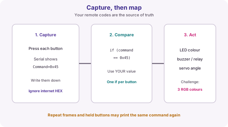
Remotes are not interchangeable by button label. Press each key you care about and write down the printed Command HEX. Only then compare IrReceiver.decodedIRData.command to those constants and drive LEDs, buzzers or other outputs.
Ignore random code tables from websites unless they match your handset. Held buttons may produce repeats - for simple labs, mapping the first printed command is enough.
// After capture, replace 0x45 / 0x46 with YOUR commands
if (IrReceiver.decodedIRData.command == 0x45) {
  // action A
} else if (IrReceiver.decodedIRData.command == 0x46) {
  // action B
}
Wiring and safe build sequence
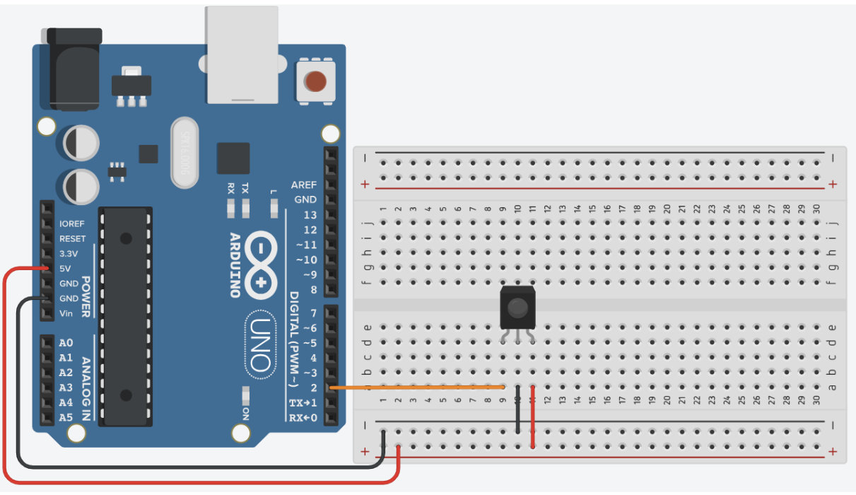
- Receiver VCC -> module-rated supply (commonly 5 V)
- GND -> GND
- OUT -> D2
- Confirm pin labels before applying power
Worked sketch
Download .ino sketch#include <IRremote.hpp>
const byte receivePin = 2;
void setup() {
Serial.begin(9600);
IrReceiver.begin(receivePin, ENABLE_LED_FEEDBACK);
}
void loop() {
if (IrReceiver.decode()) {
Serial.print("Protocol=");
Serial.print(getProtocolString(IrReceiver.decodedIRData.protocol));
Serial.print(" Command=0x");
Serial.println(IrReceiver.decodedIRData.command, HEX);
IrReceiver.resume();
}
}How the code works
- Print protocol and command from your own remote before mapping actions.
- Command values are easier to map than copying arbitrary example raw codes.
- resume prepares the receiver for the next frame - call it after you finish using the data.
Test and record evidence
Practical evidence checklist
Common faults and checks
- Verify receiver pin order against the module labels.
- Avoid direct sunlight or strong fluorescent interference on the dome.
- Confirm installed IRremote major version is 4.x with IRremote.hpp.
- Aim the remote at the receiver and try closer range.
- If only one press works, check that resume() is called after decode.
Check your understanding
Q1. Why capture your own codes?
Show answer
Commands vary between remote models.
Q2. What does IrReceiver.resume do?
Show answer
Re-arms reception for the next message.
Q3. Why is pin order important on the receiver?
Show answer
VCC, GND and OUT order varies between packages.
Q4. What does the 38 kHz carrier help with?
Show answer
It helps the module reject ordinary ambient light as a remote signal.