
17. I2C, Address Scanning & I2C LCD
Share a two-wire bus and simplify display wiring.
Learning outcomes
- Explain SDA, SCL, addresses and pull-ups on the Uno
- Compare parallel LCD wiring with an I2C backpack
- Scan or confirm a backpack address (often 0x27 or 0x3F)
- Drive a 16x2 I2C LCD with LiquidCrystal I2C by Frank de Brabander
Parts and preparation
Uno, I2C LCD backpack/display and jumper wires. Install LiquidCrystal I2C by Frank de Brabander (see Libraries box).
Before power: inspect wiring, confirm supply voltage and ensure all connected circuits share GND.
Libraries for this lesson
In Arduino IDE 2 open Tools → Manage Libraries…. Search by the Library Manager name and install the package by the exact author below. Similar names from other authors can use different APIs and will break the example.
| Include | Library Manager name | Author | Install note |
|---|---|---|---|
Wire.h | Wire | Arduino | Built into the Arduino core. No Library Manager install required. |
LiquidCrystal_I2C.h | LiquidCrystal I2C | Frank de Brabander | Install via Library Manager. Other LiquidCrystal_I2C packages use different APIs (init vs begin). |
What I2C adds
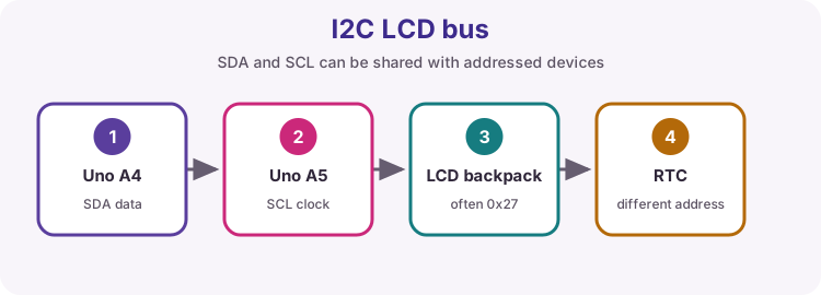
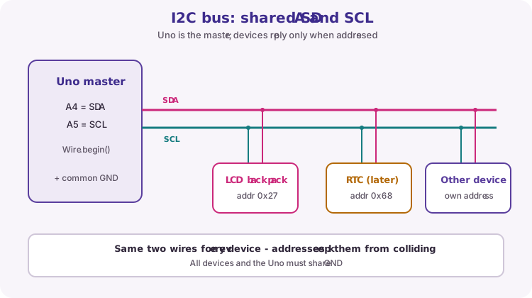
I2C is a two-wire serial bus: SDA carries data and SCL carries a shared clock. On the Uno, SDA is A4 and SCL is A5.
Several devices can share those same two wires because each device has its own address. The Uno (master) calls a device by address; only that device answers.
Parallel LCD vs I2C backpack
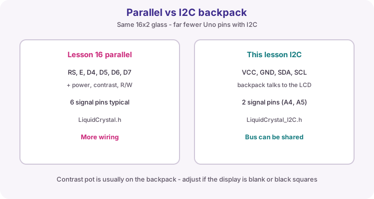
Lesson 16 drove the HD44780 with RS, E and four data lines. An I2C backpack sits on the LCD and talks over SDA/SCL instead, so the Uno only needs VCC, GND, SDA and SCL.
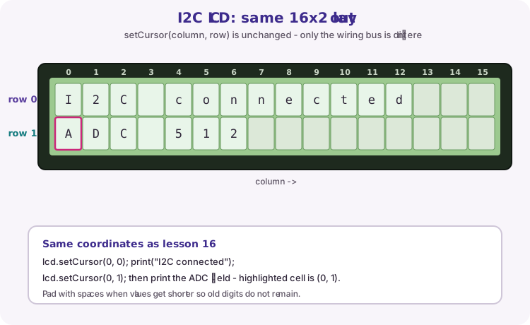
The character grid is still 16 columns by 2 rows. setCursor(column, row) works the same way.
Pull-ups
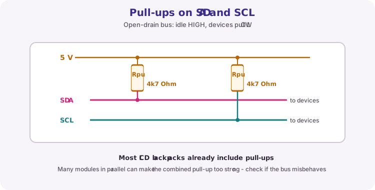
SDA and SCL are open-drain: devices only pull a line LOW. Pull-up resistors to 5 V hold the idle state HIGH. Most LCD backpacks already include those resistors.
Many modules on one bus can make the combined pull-up too strong. If the bus becomes unreliable with several devices, check module documentation and pull-up strategy.
Addresses and scanning
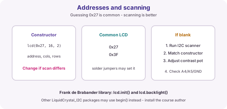
The constructor includes the backpack address, columns and rows: LiquidCrystal_I2C lcd(0x27, 16, 2). Common backpack addresses are 0x27 and 0x3F; solder pads on the backpack can change this.
If the screen stays blank, run an I2C scanner sketch, match the constructor to the reported address, and adjust the backpack contrast potentiometer.
| Item | Course practice |
|---|---|
| Library | LiquidCrystal I2C by Frank de Brabander |
| Init API | lcd.init() and lcd.backlight() |
| Default try | 0x27, then 0x3F if needed |
| Uno pins | SDA A4, SCL A5, shared GND |
Same 16x2 coordinates
setCursor(column, row) is still zero-based: columns 0-15, rows 0-1. The worked sketch prints a heading on row 0, then updates an ADC field on row 1. Pad with spaces when numbers get shorter so leftover digits do not remain.
Library variation
Several Library Manager packages use similar names. This course uses LiquidCrystal I2C by Frank de Brabander (init/backlight). A different author's package may expect begin() instead and will not compile or run with this sketch.
Wiring and safe build sequence
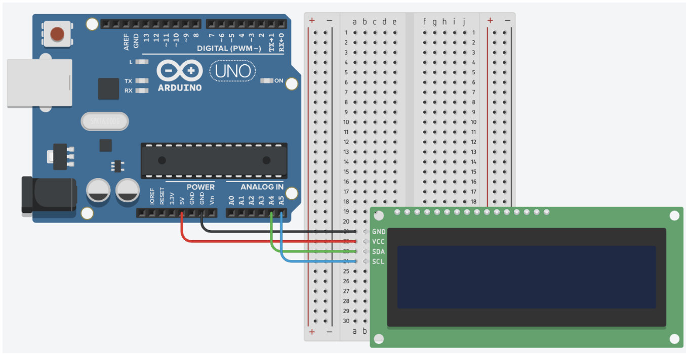
- LCD VCC -> 5 V
- LCD GND -> GND
- LCD SDA -> A4
- LCD SCL -> A5
Worked sketch
Download .ino sketch#include <Wire.h>
#include <LiquidCrystal_I2C.h>
LiquidCrystal_I2C lcd(0x27, 16, 2);
void setup() {
Wire.begin();
lcd.init();
lcd.backlight();
lcd.setCursor(0, 0);
lcd.print("I2C connected");
}
void loop() {
lcd.setCursor(0, 1);
lcd.print("ADC ");
lcd.print(analogRead(A0));
lcd.print(" ");
delay(250);
}How the code works
- Change 0x27 only if a scanner reports another address.
- All devices on the bus share SDA, SCL and GND.
- Trailing spaces clear leftover ADC digits when the value gets shorter.
Test and record evidence
Practical evidence checklist
Common faults and checks
- Run an I2C scanner if the display is blank.
- Adjust the backpack contrast potentiometer.
- Confirm the installed library's initialization API (init vs begin).
- Check A4/A5 are not swapped and GND is common.
Check your understanding
Q1. Why can devices share SDA and SCL?
Show answer
Each device responds to its own I2C address.
Q2. Which Uno pins are SDA and SCL?
Show answer
A4 is SDA and A5 is SCL.
Q3. What should you do if 0x27 shows nothing?
Show answer
Scan the bus, try the reported address, and adjust contrast.
Q4. Does I2C change the 16x2 cursor rules?
Show answer
No - columns are still 0-15 and rows 0-1.