
03. Arduino IDE 2 & First Upload
Install Arduino IDE 2, select board and port, Verify, Upload, and blink the onboard LED.
Learning outcomes
- Install and navigate Arduino IDE 2
- Select the correct board definition and serial port
- Explain the difference between Verify (compile) and Upload
- Run the Blink sketch on LED_BUILTIN and diagnose common upload faults
- Know when Library Manager is needed for later lessons
Parts and preparation
Arduino Uno, USB data cable and Arduino IDE 2 (desktop). No breadboard required for Blink.
Before power: inspect wiring, confirm supply voltage and ensure all connected circuits share GND.
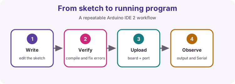
Your first reliable workflow
Arduino IDE 2 is where you write sketches, compile them, and send them to the board. A repeatable habit prevents most beginner frustration: correct board, correct port, Verify until clean, then Upload, then observe.
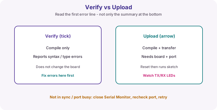
Verify vs Upload
Verify (tick icon) compiles your C++ sketch on the computer and reports syntax or type errors. It does not change what is running on the Uno.
Upload compiles (if needed) and transfers the binary through the selected port. The board resets and then runs the new program from setup() into loop().
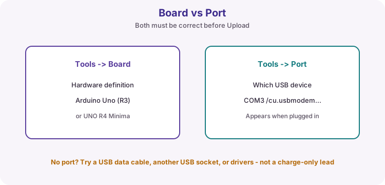
Board and port
Tools -> Board selects the hardware definition (Arduino Uno for classic R3, or UNO R4 Minima if that is your board). Wrong board choice causes confusing compile or upload failures.
Tools -> Port selects which USB device receives the upload. The port usually appears only when a data cable is connected. Charge-only cables look plugged in but never enumerate a port.
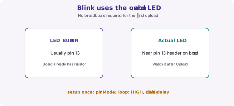
Blink and LED_BUILTIN
The classic first sketch blinks the onboard L LED. LED_BUILTIN is a named constant for that pin (usually 13 on Uno). The board already includes a series resistor for L - no breadboard required.
setup() runs once after reset and configures the pin. loop() turns the LED on, waits, turns it off, waits, and repeats.
void setup() {
  pinMode(LED_BUILTIN, OUTPUT);
}

void loop() {
  digitalWrite(LED_BUILTIN, HIGH);
  delay(1000);
  digitalWrite(LED_BUILTIN, LOW);
  delay(1000);
}
Reading error messages
Always read the first compiler error - later messages are often knock-on effects. Missing semicolons are often reported on the next line. Case matters: setup, pinMode, HIGH and LOW must match exactly.
Upload errors such as not in sync or port busy: close Serial Monitor and other programs using the port, recheck Board/Port, try another USB socket or data cable, then retry.
| Symptom | Likely fix |
|---|---|
| No port listed | Data cable; reconnect; drivers; another USB socket |
| Wrong board | Tools -> Board -> Arduino Uno (or R4 Minima) |
| Compile error | Read first error; check ; and spelling |
| Upload not in sync | Close Monitor; correct port; retry |
Library Manager (preview)
Later lessons install third-party libraries with Tools -> Manage Libraries. Each of those lessons names the exact Library Manager title and author. Install only that package - similarly named libraries often use different APIs.
Blink itself needs no extra library.
Wiring and safe build sequence
- Connect Uno to the PC with a USB data cable
- Tools -> Board -> Arduino Uno (or UNO R4 Minima if that is your board)
- Tools -> Port -> choose the port that appears when the Uno is connected
- Open File -> Examples -> 01.Basics -> Blink (or paste the worked sketch)
- Click Verify, then Upload; watch the onboard L LED
Worked sketch
Download .ino sketchvoid setup() {
pinMode(LED_BUILTIN, OUTPUT);
}
void loop() {
digitalWrite(LED_BUILTIN, HIGH); // LED on
delay(1000);
digitalWrite(LED_BUILTIN, LOW); // LED off
delay(1000);
}How the code works
- LED_BUILTIN maps to the board onboard LED pin (usually 13).
- setup runs once after reset; loop repeats for as long as the board is powered.
- delay(1000) waits one second - fine for Blink; later lessons introduce millis for multi-task timing.
- No breadboard is required for this first upload.
Test and record evidence
Practical evidence checklist
Common faults and checks
- Port not found: reconnect with a known data cable; try another USB port.
- Not in sync: verify Uno and port selections, close other serial programs, retry.
- Compilation error: read the first error, not only the final summary.
- Upload OK but no blink: confirm you uploaded Blink (not an empty sketch) and look at the L LED near pin 13.
Check your understanding
Q1. What does Verify do?
Show answer
Compiles the sketch and reports errors without uploading.
Q2. What is the difference between board and port selection?
Show answer
Board selects the target hardware definition; port selects the connected USB device.
Q3. What does LED_BUILTIN refer to?
Show answer
The pin connected to the board onboard LED (usually pin 13 on Uno).
Q4. Name one common cause of a missing port.
Show answer
A charge-only USB cable, missing drivers, or the board not connected.
Q5. Why read the first compiler error first?
Show answer
Later errors are often knock-on effects of the first mistake.