
19. DS1307 RTC & Formatted Text
Keep calendar time through power loss and format it for displays.
Learning outcomes
- Distinguish millis uptime from an RTC calendar clock
- Identify DS1307 module parts: chip, crystal, I2C and backup cell
- Wire a DS1307 on Uno I2C (A4/A5) and confirm begin succeeds
- Set time only when the clock stopped (isrunning) or lost power (lostPower)
- Format fixed-width date/time text with snprintf and %02d
Parts and preparation
Uno, DS1307 RTC module, suitable backup cell (often CR2032), and RTClib by Adafruit (see Libraries box).
Before power: inspect wiring, confirm supply voltage and ensure all connected circuits share GND.
Libraries for this lesson
In Arduino IDE 2 open Tools → Manage Libraries…. Search by the Library Manager name and install the package by the exact author below. Similar names from other authors can use different APIs and will break the example.
| Include | Library Manager name | Author | Install note |
|---|---|---|---|
Wire.h | Wire | Arduino | Built into the Arduino core. No Library Manager install required. |
RTClib.h | RTClib | Adafruit | Install via Library Manager. Choose Adafruit, not similarly named RTC packages. |
millis is not a wall clock
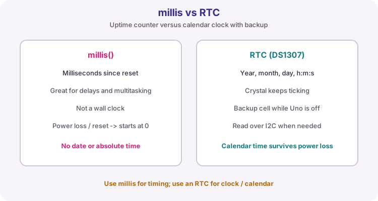
millis() counts milliseconds since the Uno last reset. It is excellent for non-blocking delays and multitasking (lesson 28), but it is not a calendar clock. After power loss or reset it starts from zero again, with no idea of the real date or time of day.
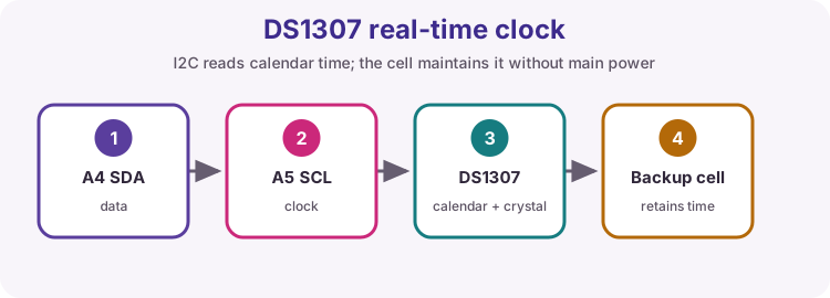
A real-time clock (RTC) chip keeps year, month, day, hour, minute and second. A backup cell on the module keeps that calendar running while the Uno is unpowered.
What is on a DS1307 module
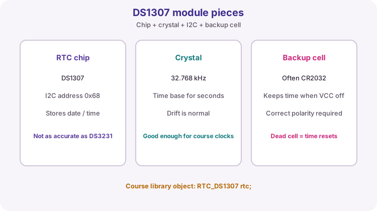
Course modules usually include a DS1307 chip, a 32.768 kHz crystal, I2C pins and a coin-cell holder. The chip talks over I2C at address 0x68. The crystal is the time base; drift of seconds per day is normal for this part.
A DS3231 is a more accurate, temperature-compensated alternative. This lesson uses RTC_DS1307 from Adafruit RTClib. If your kit is a DS3231, keep the same wiring and swap the object type: comment out RTC_DS1307 and use RTC_DS3231 instead.
| Item | Course practice |
|---|---|
| Library | RTClib by Adafruit |
| Object (DS1307) | RTC_DS1307 rtc |
| Object (DS3231) | RTC_DS3231 rtc |
| I2C address | Usually 0x68 |
| Accuracy note | DS1307 drifts more than DS3231 |
I2C wiring on the Uno
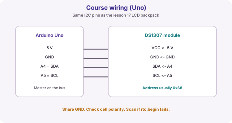
Wire VCC to 5 V, GND to GND, SDA to A4 and SCL to A5 - the same bus pins as the I2C LCD in lesson 17. Share GND with every device on the bus. Install the backup cell with the correct polarity before you rely on power-loss tests.
If rtc.begin() fails, check wiring first, then run an I2C scanner. A missing address usually means a bad connection, wrong module, or power issue - not a Serial formatting bug.
| Module pin | Uno |
|---|---|
| VCC | 5 V |
| GND | GND |
| SDA | A4 |
| SCL | A5 |
| Backup cell | Correct type and polarity |
Set time only when needed
rtc.adjust(DateTime(F(__DATE__), F(__TIME__))) writes the PC compile date and time into the RTC. If you call adjust on every boot, the clock jumps back to that compile moment after every reset.
Safer pattern: adjust only when the chip reports that it is not running or that it lost battery power. For RTC_DS1307 use !rtc.isrunning(). For RTC_DS3231 use rtc.lostPower() instead. Once the backup cell is good and the clock is running, later uploads leave the time alone.
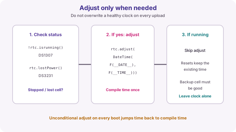
// Automatically sets time ONLY if the clock stopped or lost battery power
if (!rtc.isrunning()) {  // For DS3231, use: if (rtc.lostPower())
  rtc.adjust(DateTime(F(__DATE__), F(__TIME__)));
}
Fixed-width text with snprintf
DateTime fields are integers. For Serial or an LCD you usually want a fixed-width string such as 30/07/2026 21:54:03 so columns do not jump when values are single-digit.
snprintf writes into a char buffer and takes the buffer size so it does not write past the end. %02d pads to two digits; %04d keeps a four-digit year. char line[24] is enough for this course format plus the terminating NUL.
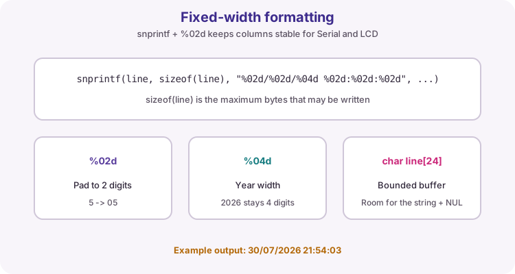
DateTime now = rtc.now();
snprintf(line, sizeof(line), "%02d/%02d/%04d %02d:%02d:%02d",
         now.day(), now.month(), now.year(),
         now.hour(), now.minute(), now.second());
Serial.println(line);
Wiring and safe build sequence
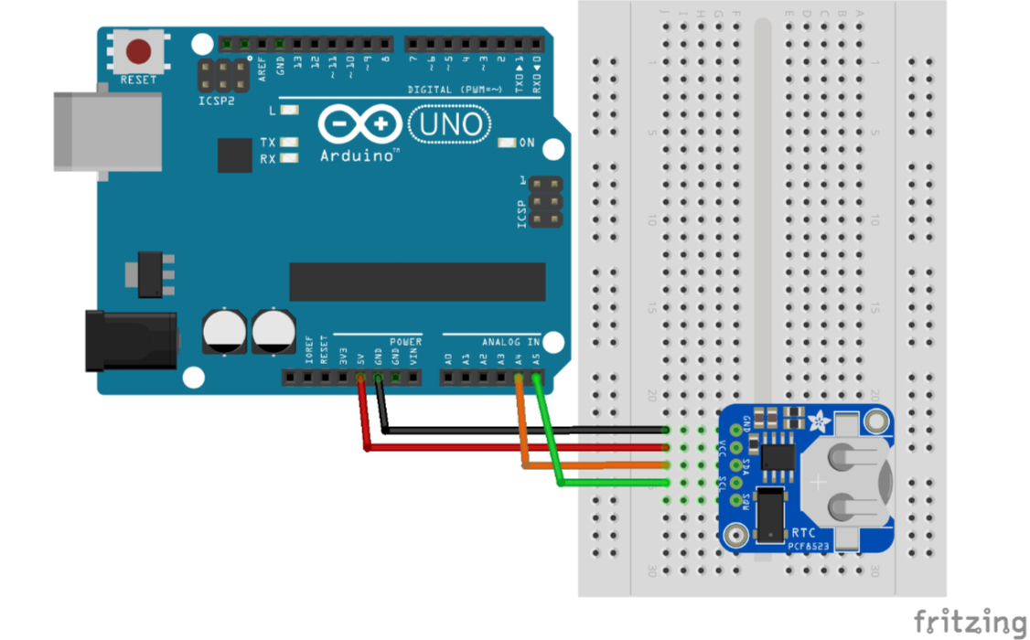
- RTC VCC -> 5 V
- RTC GND -> GND
- RTC SDA -> A4
- RTC SCL -> A5
- Install the correct backup cell with correct polarity
Worked sketch
Download .ino sketch#include <Wire.h>
#include <RTClib.h>
RTC_DS1307 rtc;
// RTC_DS3231 rtc; // use this instead if your module is a DS3231
char line[24];
void setup() {
Serial.begin(9600);
if (!rtc.begin()) {
Serial.println("RTC not found");
while (true) { delay(100); }
}
// Automatically sets time ONLY if the clock stopped or lost battery power
if (!rtc.isrunning()) { // For DS3231, use: if (rtc.lostPower())
rtc.adjust(DateTime(F(__DATE__), F(__TIME__)));
}
}
void loop() {
DateTime now = rtc.now();
snprintf(line, sizeof(line), "%02d/%02d/%04d %02d:%02d:%02d",
now.day(), now.month(), now.year(),
now.hour(), now.minute(), now.second());
Serial.println(line);
delay(1000);
}How the code works
- sizeof(line) prevents snprintf from writing beyond the buffer.
- The RTC not found message points to wiring or address faults, not formatting.
- isrunning (DS1307) or lostPower (DS3231) gates adjust so a healthy clock is not overwritten.
- For a DS3231 module, comment RTC_DS1307, uncomment RTC_DS3231, and use lostPower().
Test and record evidence
Practical evidence checklist
Common faults and checks
- Use an I2C scanner to confirm the RTC address (usually 0x68).
- Replace or reseat the backup cell if time resets when the Uno loses power.
- If time jumps after every upload, check you are not calling adjust unconditionally.
- Confirm SDA is A4 and SCL is A5 on the Uno, with shared GND.
- Install Adafruit RTClib, not a differently named RTC package.
- Match the object type and check: RTC_DS1307 + isrunning, or RTC_DS3231 + lostPower.
Check your understanding
Q1. Why not use millis as a clock?
Show answer
It measures uptime only and resets after power loss/reset.
Q2. When should rtc.adjust run?
Show answer
Only when the clock stopped (isrunning) or lost power (lostPower).
Q3. Which Uno pins are SDA and SCL?
Show answer
A4 (SDA) and A5 (SCL).
Q4. What does %02d do in snprintf?
Show answer
It prints an integer padded to two digits.