
16. 16x2 LCD in 4-Bit Mode
Display text and live values on a character LCD.
Learning outcomes
- Explain LCD data and instruction registers
- Wire RS, E and four data lines
- Set contrast and backlight safely
- Position and update text without leftover characters
Parts and preparation
Uno, HD44780-compatible 16x2 LCD, 10 k ohm potentiometer, 220 ohm backlight resistor where required and jumpers.
Before power: inspect wiring, confirm supply voltage and ensure all connected circuits share GND.
Libraries for this lesson
In Arduino IDE 2 open Tools → Manage Libraries…. Search by the Library Manager name and install the package by the exact author below. Similar names from other authors can use different APIs and will break the example.
| Include | Library Manager name | Author | Install note |
|---|---|---|---|
LiquidCrystal.h | LiquidCrystal | Arduino | Built-in with Arduino AVR Boards. No Library Manager install required. |
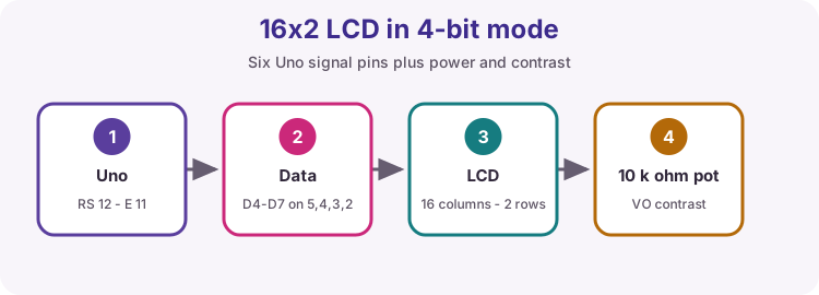
Interface
RS selects command or data, E latches a transfer, and D4D7 carry four bits at a time. R/W is normally tied to GND for write-only operation.
Contrast
VO needs an adjustable voltage from a potentiometer. A row of solid blocks usually means power and contrast are present but initialization/data wiring is wrong.
Coordinates
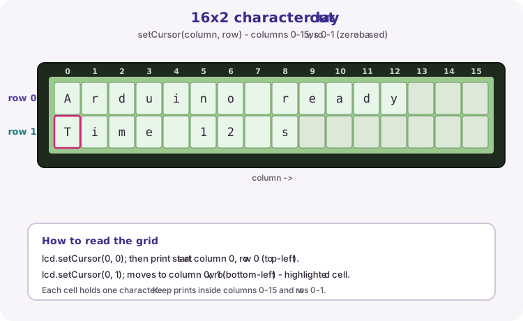
setCursor(column, row) uses zero-based positions. A 16x2 display has columns 0-15 (left to right) and rows 0-1 (top then bottom).
After begin(16, 2), print() continues from the current cursor. The worked sketch prints on row 0 from the default top-left, then uses setCursor(0, 1) for the seconds line.
| Call | Starts writing at |
|---|---|
| setCursor(0, 0) | Column 0, row 0 (top-left) |
| setCursor(0, 1) | Column 0, row 1 (bottom-left) |
| setCursor(15, 0) | Last column on the top row |
| print("Hi") | Two cells from the current cursor |
Updating text
Printing a shorter value leaves old characters behind. Pad with spaces or overwrite the full field.
Wiring and safe build sequence
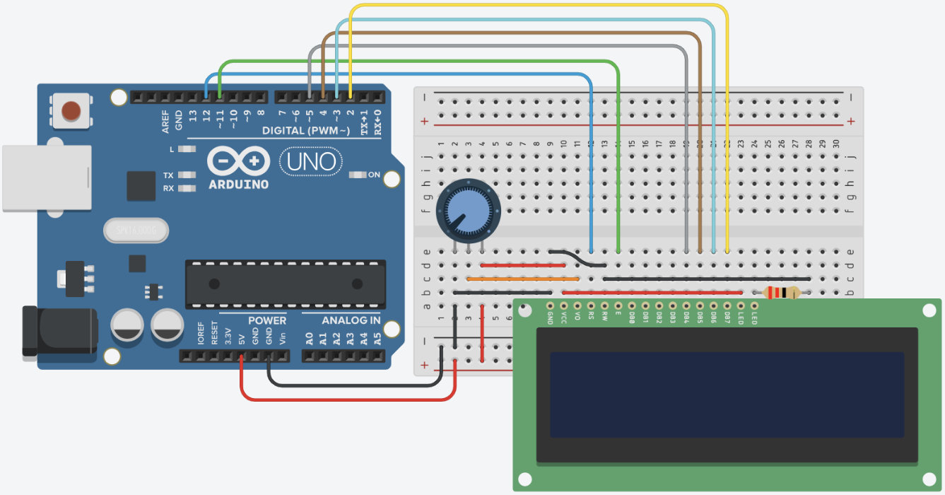
- VSS -> GND, VDD -> 5 V, R/W -> GND
- 10 k ohm pot ends -> 5 V/GND; wiper -> VO
- RS -> D12, E -> D11
- D4-D7 -> D5, D4, D3, D2
- Backlight through resistor if the module does not include one
Worked sketch
Download .ino sketch#include <LiquidCrystal.h>
LiquidCrystal lcd(12, 11, 5, 4, 3, 2);
void setup() {
lcd.begin(16, 2);
lcd.print("Arduino ready");
}
void loop() {
lcd.setCursor(0, 1);
lcd.print("Time ");
lcd.print(millis() / 1000);
lcd.print(" s ");
delay(200);
}How the code works
- Constructor order must match RS, E, D4, D5, D6, D7 wiring.
- Trailing spaces erase digits left by a longer previous number.
Test and record evidence
Practical evidence checklist
Common faults and checks
- Adjust contrast before changing code.
- Check R/W is grounded.
- If text is scrambled, verify D4D7 order.
Check your understanding
Q1. What does RS select?
Show answer
The instruction register or data register.
Q2. Why print trailing spaces?
Show answer
To erase characters from a longer previous value.