
07. Digital Outputs, RGB LEDs & Buzzers
Drive LEDs safely, mix RGB colour, and play tones on a passive buzzer.
Learning outcomes
- Use pinMode OUTPUT and digitalWrite HIGH/LOW correctly
- Limit LED current with a series resistor on each channel
- Explain common-cathode versus common-anode RGB wiring and logic
- Distinguish active and passive buzzers and use tone / noTone
- Recognise loads that need a driver instead of a bare Uno pin
Parts and preparation
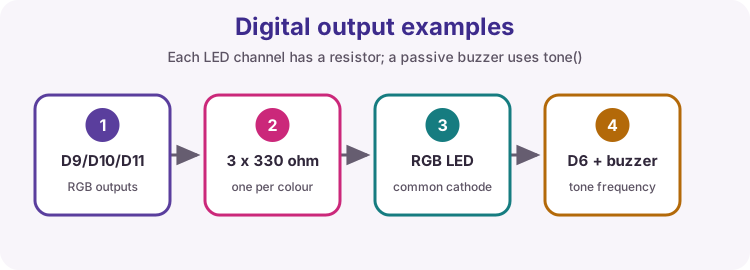
Uno, common-cathode RGB LED (or separate red/green/blue LEDs), 3 x 330 ohm resistors, passive piezo buzzer, breadboard and jumpers.
Before power: inspect wiring, confirm supply voltage and ensure all connected circuits share GND.
What a digital output does
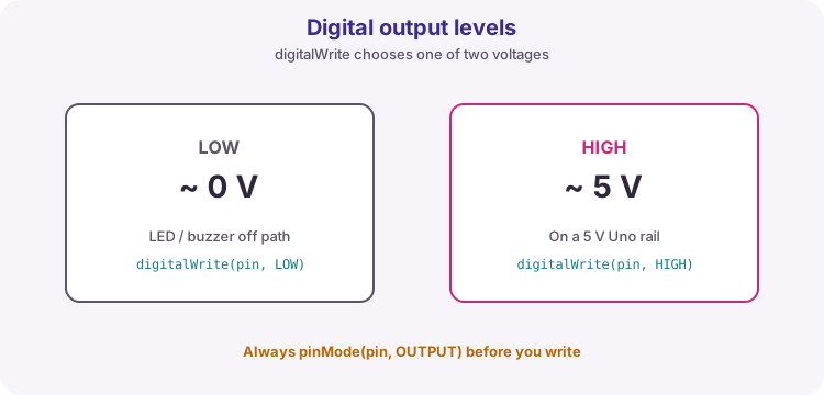
After pinMode(pin, OUTPUT), digitalWrite chooses a logic level. On a 5 V Uno, LOW is about 0 V and HIGH is about 5 V.
That is enough for indicator LEDs (with resistors) and for signalling other logic chips. It is not a power supply for motors, heaters or big lamps.
Safe loads vs drivers
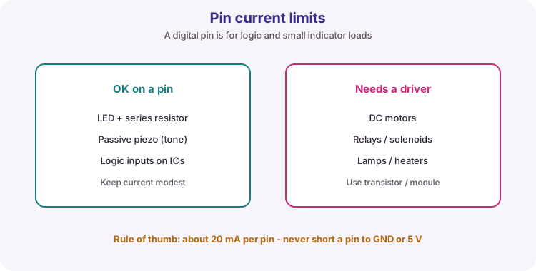
A classic Uno pin is rated for modest current (plan around 20 mA per pin, and stay well under absolute maxima). Always use a series resistor with an LED.
Motors, relays, solenoids and heaters need a transistor, MOSFET or driver module plus a suitable supply - and often a flyback diode. Lesson 12 covers drivers in more depth.
RGB LEDs: three dies, three resistors
An RGB LED packs red, green and blue emitters. Each colour needs its own series resistor - sharing one resistor for all three is incorrect and uneven.
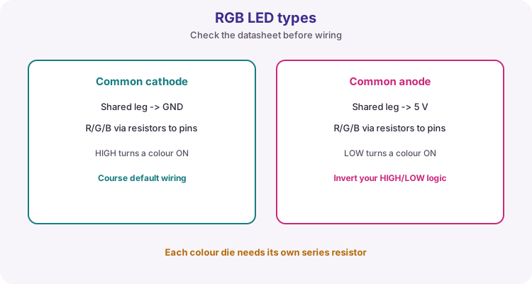
Course wiring assumes common cathode: the shared leg goes to GND, and each colour leg goes through 330 ohm to a digital pin. HIGH turns that colour on.
| Signal | Course pin | Role |
|---|---|---|
| Red | D9 | Red channel via 330 ohm |
| Green | D10 | Green channel via 330 ohm |
| Blue | D11 | Blue channel via 330 ohm |
| Buzzer | D6 | Passive piezo + tone() |
Common cathode vs common anode
Common cathode: shared pin to GND; drive colours HIGH to light. That is this lesson's default.
Common anode: shared pin to 5 V; drive colours LOW to light (active-low). If your RGB looks always-on or inverted, you may have the other type - check the datasheet and invert the logic.
Active vs passive buzzers
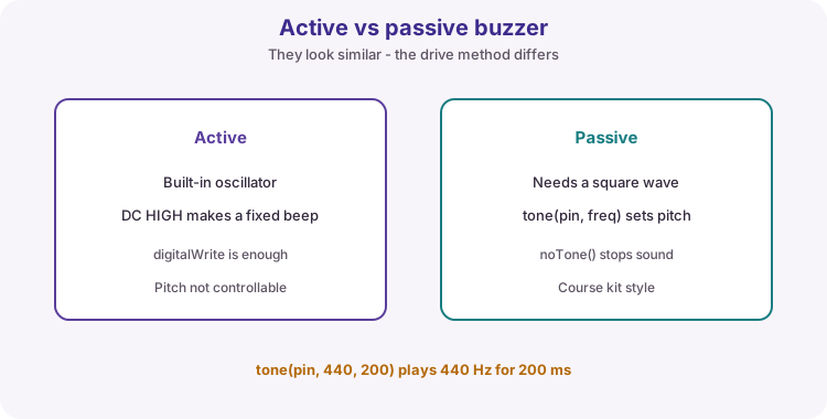
An active buzzer has a built-in oscillator: a steady HIGH makes a fixed beep. A passive piezo is closer to a speaker: it needs a square wave at an audible frequency.
Arduino tone(pin, frequency) generates that wave. An optional third argument is duration in milliseconds. noTone(pin) stops sound. This course uses a passive buzzer with tone().
tone(buzzerPin, 440, 200);  // A4, 200 ms
delay(250);
noTone(buzzerPin);
What the worked sketch practises
The sketch cycles red, green and blue with a different tone for each step. Only one colour is HIGH at a time so you can confirm each channel and hear pitch changes.
Try mixing colours later by turning two pins HIGH together (yellow ≈ red+green).
Wiring and safe build sequence
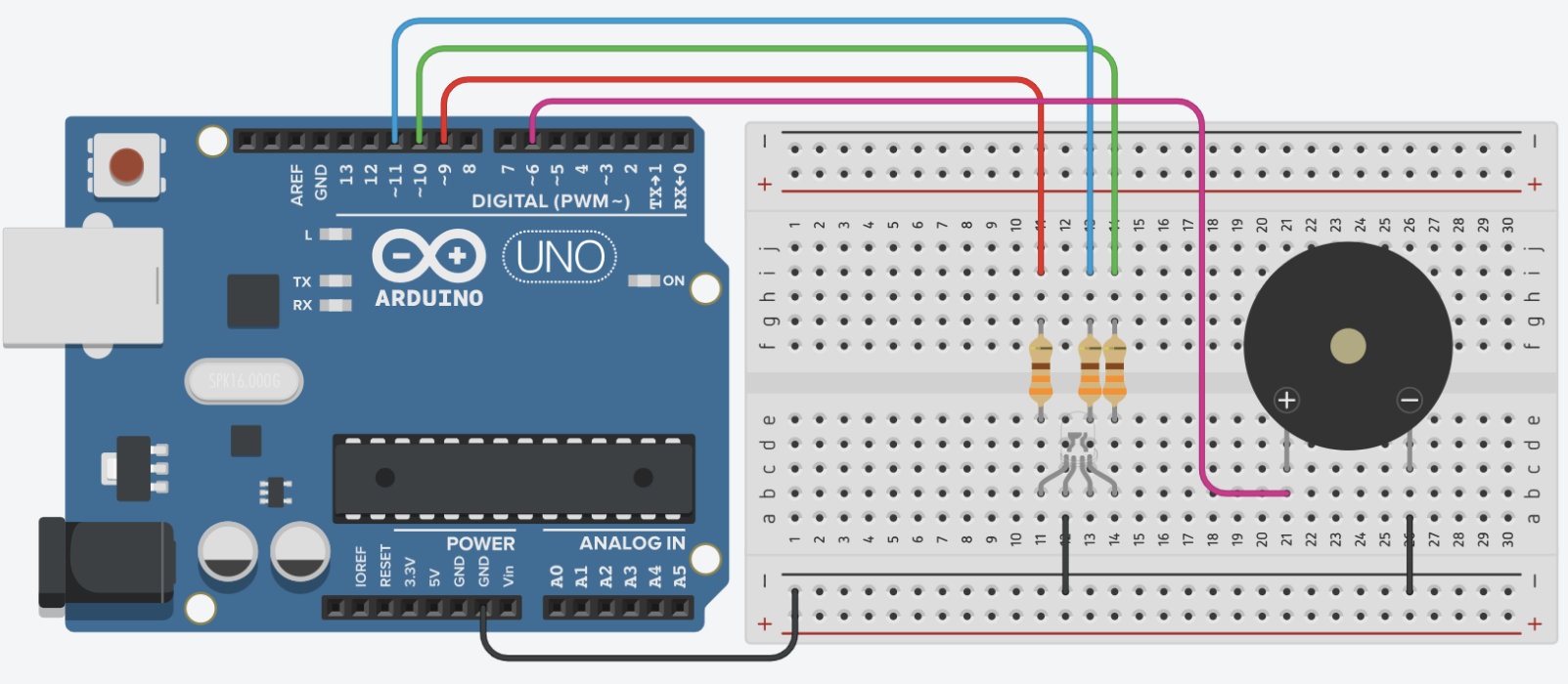
- RGB common cathode -> GND (confirm datasheet if unmarked)
- Red leg -> 330 ohm -> D9
- Green leg -> 330 ohm -> D10
- Blue leg -> 330 ohm -> D11
- Passive buzzer + -> D6; buzzer - -> GND
- If colours are inverted or always on, you may have a common-anode LED - invert HIGH/LOW
Worked sketch
Download .ino sketchconst byte redPin = 9;
const byte greenPin = 10;
const byte bluePin = 11;
const byte buzzerPin = 6;
void allOff() {
digitalWrite(redPin, LOW);
digitalWrite(greenPin, LOW);
digitalWrite(bluePin, LOW);
}
void setup() {
pinMode(redPin, OUTPUT);
pinMode(greenPin, OUTPUT);
pinMode(bluePin, OUTPUT);
// tone() does not require pinMode, but OUTPUT is fine if you also digitalWrite
pinMode(buzzerPin, OUTPUT);
allOff();
}
void loop() {
allOff();
digitalWrite(redPin, HIGH);
tone(buzzerPin, 440, 200);
delay(500);
allOff();
digitalWrite(greenPin, HIGH);
tone(buzzerPin, 660, 200);
delay(500);
allOff();
digitalWrite(bluePin, HIGH);
tone(buzzerPin, 880, 200);
delay(500);
}How the code works
- allOff clears every colour before lighting the next - easier to see each channel.
- tone duration is in milliseconds; delay should be a little longer if you want a gap.
- Each RGB colour needs its own resistor even when only one colour is on.
- For common-anode RGB, swap the sense of HIGH and LOW (or write a small helper).
Test and record evidence
Practical evidence checklist
Common faults and checks
- Verify RGB pinout from the module datasheet - long leg is not always common.
- A common-anode LED needs inverted HIGH/LOW logic compared with this sketch.
- No sound: confirm a passive buzzer (not active-only) and polarity; try a known frequency like 1000.
- Only one colour works: check that channel's resistor and pin number.
- USB brown-out or reset when wiring: you may have shorted a pin - disconnect and recheck.
Check your understanding
Q1. Why does each RGB channel need a resistor?
Show answer
Each LED die needs its own current limiting.
Q2. What does tone control on a passive buzzer?
Show answer
The frequency of the square wave (the pitch).
Q3. How does common-anode drive differ from common-cathode?
Show answer
Shared leg to 5 V; colours turn on with LOW instead of HIGH.
Q4. Why not drive a DC motor from a digital pin directly?
Show answer
Current and inductive kick exceed what a logic pin should supply - use a driver.
Q5. What does allOff achieve in the sketch?
Show answer
It turns every colour channel LOW before the next colour so only one shows at a time.