
02. Microcontrollers & the Arduino Uno
Meet the computer on the Uno: MCU vs PC, power pins, I/O groups, R3 vs R4, and optional bare-chip essentials.
Learning outcomes
- Distinguish a microcontroller from a microprocessor system
- Identify Uno R3 and R4 Minima power pins, I/O and on-board LEDs
- Choose a safe power connection (USB, VIN / barrel)
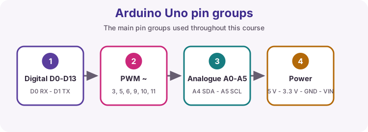
- Explain digital, analogue, UART, I2C and SPI pin roles
- Compare key R3 and R4 Minima specs used in this course
- Describe the minimum parts for an ATmega328P on a breadboard
Parts and preparation
Arduino Uno R3 (course default) or Uno R4 Minima, and a USB data cable. Optional extension: ATmega328P (DIP), breadboard, 16 MHz crystal, 2 x 22 pF capacitors, 10 k ohm resistor, 10 uF capacitor and a regulated 5 V supply.
Before power: inspect wiring, confirm supply voltage and ensure all connected circuits share GND.
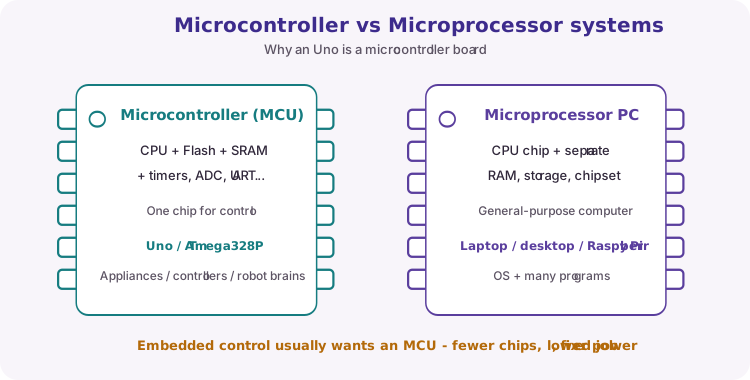
Microcontroller versus microprocessor
A microcontroller (MCU) combines a CPU, Flash program memory, SRAM, often EEPROM, and peripherals (timers, ADC, UART, and more) on one chip for a dedicated control job.
A microprocessor system (a typical PC) uses a CPU chip plus separate RAM, storage and chipsets - suited to general-purpose computing with an operating system and many programs.
An appliance controller, robot brain or Uno project usually wants an MCU: fewer chips, lower power, fixed task.
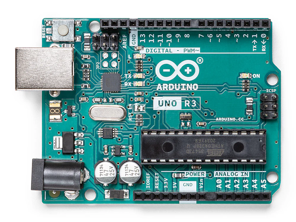
Arduino Uno R3 board guide
This course defaults to the classic Arduino Uno Rev3: ATmega328P, 5 V logic, USB-B, and the standard Uno shield layout.
| Item | Uno R3 |
|---|---|
| Microcontroller | ATmega328P @ 16 MHz |
| Flash / SRAM / EEPROM | 32 KB (about 0.5 KB bootloader) / 2 KB / 1 KB |
| Logic / USB | 5 V logic · USB-B |
| Digital I/O | D0-D13 · PWM on ~ pins 3, 5, 6, 9, 10, 11 |
| Analogue inputs | A0-A5 · 10-bit ADC (0-1023) by default |
| VIN / barrel | About 7-12 V recommended |
| I/O current (design) | About 20 mA per pin (40 mA absolute max) |
| Built-in LED (L) | Pin 13 · LED_BUILTIN |
| TX / RX LEDs | Flash on USB Serial Monitor traffic |
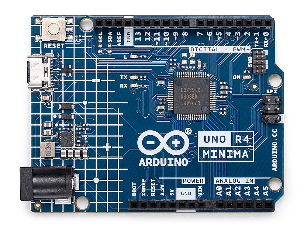
Arduino Uno R4 Minima board guide
Same Uno form factor and 5 V class as R3, but a faster Renesas RA4M1 MCU, more memory, USB-C, and extras. Select UNO R4 Minima in the IDE if you use this board.
| Item | Uno R4 Minima |
|---|---|
| Microcontroller | RA4M1 (Arm Cortex-M4) @ 48 MHz |
| Flash / SRAM / EEPROM | 256 KB / 32 KB / 8 KB |
| Logic / USB | 5 V logic · USB-C |
| Digital I/O | 14 pins · 6 PWM |
| Analogue inputs | 6 inputs · up to 14-bit resolution available |
| VIN / barrel | About 6-24 V |
| I/O current (design) | About 8 mA per pin - do not assume R3 20 mA |
| Built-in LED (L) | Pin 13 · LED_BUILTIN |
| Extras | DAC, RTC, CAN (needs transceiver), HID, SWD |
| Sketches / libraries | Arduino API sketches often work; AVR-only code may need changes |
Powering the board: USB vs VIN
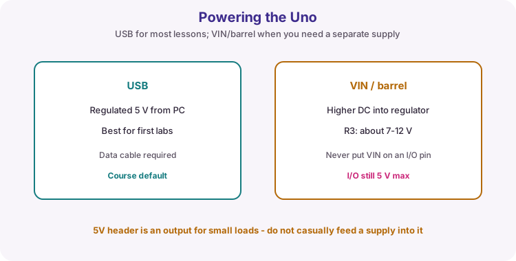
For almost every early lesson, power the Uno from USB with a data cable. That provides regulated 5 V for the MCU and small indicator circuits.
The barrel jack / VIN path feeds the onboard regulator from a higher DC voltage (R3 typically about 7-12 V recommended). Never put that higher voltage on a digital or analogue I/O pin. Treat the 5V header as an output for small loads - do not casually feed an external supply into it.
Power pins: 5V, 3.3V, VIN, AREF and GND
Both boards use the same power-header ideas. Treat these pins carefully.
| Pin | Use |
|---|---|
| 5V | Regulated 5 V for the MCU and many sensors. Power via USB or VIN/barrel. |
| 3.3V / 3V3 | 3.3 V for suitable modules (limited current). Never put 5 V into a 3.3 V-only device. |
| GND | Common 0 V. Every external circuit must share GND with the Uno. |
| VIN | Raw board input (barrel). Not a sensor logic output. |
| AREF | ADC reference. Default analogue range about 0-5 V. Leave open until a lesson uses analogReference(). |
| IOREF | Tells shields the I/O voltage (5 V here). |
| RESET | Pull low to restart the sketch (reset button). |
Digital pins, analogue pins and buses
Header roles match on R3 and R4 Minima for typical shields. Memorise UART, I2C and SPI early - they return often.
| Group | Pins / notes |
|---|---|
| Digital I/O | D0-D13 · pins marked ~ support PWM (analogWrite) |
| UART / USB Serial | D0 RX, D1 TX - avoid for buttons/LEDs while using Serial Monitor |
| Analogue in | A0-A5 · R3 default 10-bit (0-1023) |
| I2C | A4 SDA, A5 SCL |
| SPI | D13 SCK, D12 MISO, D11 MOSI, D10 SS |
| External interrupts | Commonly D2 and D3 on Uno-class boards |
Uno R3 versus R4 Minima
Same family layout and 5 V class, different microcontroller and limits. This course targets Uno R3 unless a note says otherwise - if you use R4 Minima, select that board in the IDE and watch pin-current limits.
| Feature | Uno R3 | Uno R4 Minima |
|---|---|---|
| Microcontroller | ATmega328P (8-bit AVR) | Renesas RA4M1 (Arm Cortex-M4) |
| Clock | 16 MHz | 48 MHz |
| Flash / SRAM / EEPROM | 32 KB / 2 KB / 1 KB | 256 KB / 32 KB / 8 KB |
| Logic voltage | 5 V | 5 V |
| USB | USB-B | USB-C |
| I/O pin current (design) | About 20 mA (40 mA abs. max) | About 8 mA |
| Extras | ICSP, shield ecosystem | DAC, RTC, CAN, HID, SWD |
Electrical limits
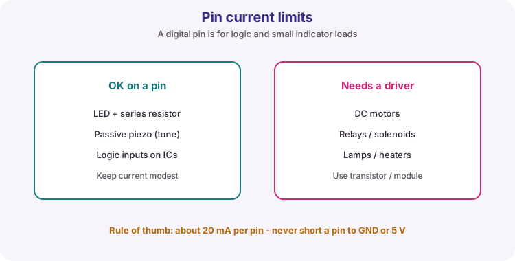
Both boards use 5 V logic on I/O - never apply more than 5 V to a digital or analogue pin. On Uno R3 design for about 20 mA or less per pin (40 mA is an absolute maximum, not a target). On Uno R4 Minima assume a lower per-pin budget (about 8 mA) and use drivers for heavier loads. Total chip current limits still apply.
ATmega328P on a breadboard
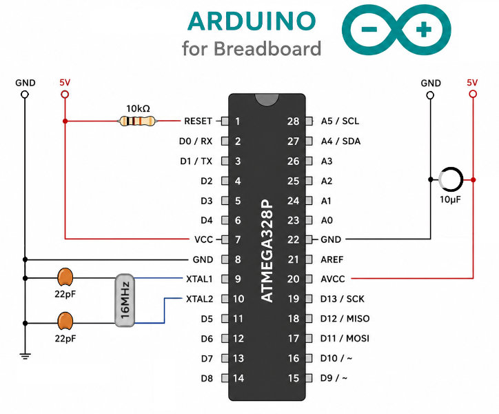
The Uno R3 board is mainly power regulation, USB-to-serial, a crystal clock, reset support and labelled headers around the ATmega328P chip. You can run that chip alone on a breadboard if you add the same essentials: a stable 5 V supply, ground, a 16 MHz crystal with load capacitors, a reset pull-up and decoupling.
Orient the DIP package so the notch (or pin-1 dot) is at the top. Pin 1 is RESET at top-left; pins then count down the left side (1-14) and up the right side (15-28).
Minimum wiring matching the diagram: 10 k ohm from RESET (pin 1) to 5 V; VCC (pin 7) and AVCC (pin 20) to 5 V; GND (pins 8 and 22) to GND; 16 MHz crystal between XTAL1 (pin 9) and XTAL2 (pin 10); 22 pF from each crystal pin to GND; 10 uF across the 5 V and GND rails close to the chip.
This section is for understanding and optional hardware builds. Day-to-day course work still uses a ready-made Uno. The R4 Minima does not use a DIP ATmega328P - you cannot breadboard it the same way.
Wiring and safe build sequence
- USB supplies regulated 5 V for the board and small test circuits
- Uno R3: use about 7-12 V only at the barrel jack / VIN as recommended
- Uno R4 Minima: VIN may accept about 6-24 V - still never put that voltage on an I/O pin
- Never apply voltage above 5 V to a digital or analogue I/O pin
- All connected external circuits need a common GND
- Optional bare-chip build (R3 / ATmega328P only): regulated 5 V; fit crystal, 22 pF caps, 10 k ohm RESET pull-up and 10 uF rail decoupling before powering
Worked sketch
Download .ino sketchvoid setup() {
Serial.begin(9600);
Serial.println("Lesson 02: Arduino Uno ready");
}
void loop() {
Serial.print("Uptime (s): ");
Serial.println(millis() / 1000);
delay(1000);
}How the code works
- Serial uses the USB connection through the board USB-to-serial interface.
- millis returns time since reset, not calendar date/time.
- Watch the TX/RX LEDs while the Serial Monitor is open - they show USB serial activity.
- Match Monitor baud to Serial.begin(9600).
Test and record evidence
Practical evidence checklist
Common faults and checks
- Use a USB data cable, not a charging-only cable (R3 USB-B or R4 USB-C as fitted).
- Match the Serial Monitor baud rate to 9600.
- Wrong board selected in the IDE: choose Arduino Uno for R3, or Arduino UNO R4 Minima for R4.
- Bare chip dead: check 5 V on VCC and AVCC, both GNDs, crystal orientation and the 10 k ohm RESET pull-up to 5 V.
Check your understanding
Q1. Why is a microcontroller suitable for an appliance controller?
Show answer
It integrates processing, memory and I/O for a dedicated embedded task.
Q2. What do the TX and RX LEDs usually indicate on an Uno?
Show answer
USB serial communication activity with the computer (for example Serial Monitor traffic).
Q3. Name one memory or clock difference between Uno R3 and Uno R4 Minima.
Show answer
Examples: R3 has 32 KB Flash / 2 KB SRAM at 16 MHz; R4 Minima has 256 KB Flash / 32 KB SRAM at 48 MHz.
Q4. Why prefer USB power for early labs?
Show answer
It provides a convenient regulated 5 V supply and a programming/serial link without a separate barrel supply.
Q5. Name four parts needed for an ATmega328P to run on a breadboard besides the chip and 5 V/GND.
Show answer
16 MHz crystal, two 22 pF capacitors, 10 k ohm RESET pull-up and a decoupling capacitor (for example 10 uF) across the supply rails.