
28. External Interrupts
React instantly to a pin edge, then finish the work in loop().
Learning outcomes
- Identify Uno hardware interrupt pins
- Use attachInterrupt with a volatile flag
- Keep an ISR short and safe
- Handle the event in loop with non-blocking outputs
Parts and preparation
Uno, push-button, LED with 330 ohm resistor and a passive buzzer.
Before power: inspect wiring, confirm supply voltage and ensure all connected circuits share GND.
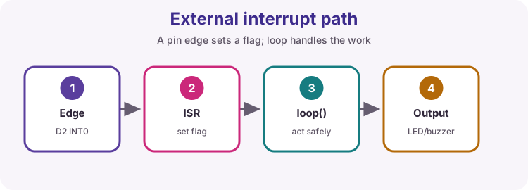
What an interrupt does
An interrupt can pause the main program when a pin edge occurs, run an ISR, then return. It is useful for rare, time-critical events such as a limit switch or encoder tick.
Uno pins
On the classic Uno, external interrupt INT0 is D2 and INT1 is D3. Many other pins need pin-change interrupts, which are more advanced.
ISR rules
Keep the ISR extremely short. Set a volatile flag or count, then return. Avoid delay, Serial printing, floating-point work and long library calls inside the ISR.
Shared data
Variables written in an ISR and read in loop must be volatile. For multi-byte values that must stay consistent, briefly disable interrupts while copying them in loop.
Wiring and safe build sequence
- Button from D2 to GND with INPUT_PULLUP
- D8 -> 330 ohm -> LED -> GND
- Passive buzzer signal -> D7; buzzer GND -> GND
Worked sketch
Download .ino sketchconst byte buttonPin = 2;
const byte ledPin = 8;
const byte buzzerPin = 7;
volatile bool eventPending = false;
volatile unsigned int eventCount = 0;
unsigned long beepUntil = 0;
bool ledOn = false;
void onButtonEdge() {
eventPending = true;
eventCount++;
}
void setup() {
pinMode(buttonPin, INPUT_PULLUP);
pinMode(ledPin, OUTPUT);
pinMode(buzzerPin, OUTPUT);
Serial.begin(9600);
attachInterrupt(digitalPinToInterrupt(buttonPin), onButtonEdge, FALLING);
}
void loop() {
if (eventPending) {
noInterrupts();
eventPending = false;
unsigned int countCopy = eventCount;
interrupts();
ledOn = !ledOn;
digitalWrite(ledPin, ledOn);
tone(buzzerPin, 1200);
beepUntil = millis() + 80;
Serial.print("Events: ");
Serial.println(countCopy);
}
if (beepUntil != 0 && millis() >= beepUntil) {
noTone(buzzerPin);
beepUntil = 0;
}
}How the code works
- FALLING matches an INPUT_PULLUP button that goes LOW when pressed.
- digitalPinToInterrupt(2) maps D2 to interrupt 0 on Uno.
- The beep duration is finished in loop with millis, not delay inside the ISR.
Test and record evidence
Practical evidence checklist
Common faults and checks
- Multiple counts per press: add software debounce in loop or a short ignore window after an event.
- No response: confirm the button is on D2 and uses INPUT_PULLUP to GND.
Check your understanding
Q1. Which Uno pins have external interrupts?
Show answer
D2 (INT0) and D3 (INT1).
Q2. What should an ISR usually do?
Show answer
Only set a flag or update a simple count, then return quickly.