
15. Stepper Motors & Drivers
Produce repeatable incremental motion.
Learning outcomes
- Compare stepper and brushed DC motor behaviour
- Explain open-loop stepping and missed-step risk
- Describe the 28BYJ-48 + ULN2003 beginner path
- Use STEP/DIR on an A4988-style driver with safe current and power practice
Parts and preparation
Uno and either 28BYJ-48 + ULN2003 or NEMA17 + A4988/DRV8825 with motor supply.
Before power: inspect wiring, confirm supply voltage and ensure all connected circuits share GND.

Stepper vs brushed DC
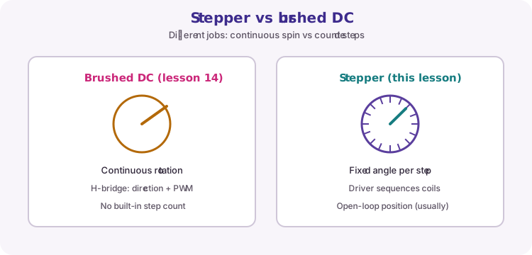
A brushed DC motor (lesson 14) spins continuously; an H-bridge sets direction and PWM sets speed. You do not get a free step count.
A stepper motor moves in fixed angular increments when its coils are energised in sequence. Count the steps (and know the step angle / microstepping) and you can estimate shaft position - as long as every commanded step actually happened.
Stepping motion and open-loop control
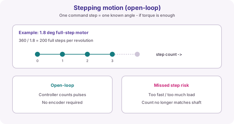
A common NEMA17 full-step angle is 1.8 degrees, so 200 full steps make one revolution. Microstepping divides each full step into smaller moves for smoother motion (more pulses per revolution).
Hobby setups are usually open-loop: the sketch assumes each STEP pulse moved the shaft. If load or speed is too high, a step can be missed and the software position drifts from reality until you home against a switch or sensor.
| Item | Typical note |
|---|---|
| 1.8 deg motor | 200 full steps / revolution |
| Microstepping | More pulses per rev; smoother, less torque per microstep |
| Open-loop | No encoder; trust the step count |
| Closed-loop | Needs a sensor / encoder (beyond this lesson) |
Beginner path: 28BYJ-48 + ULN2003
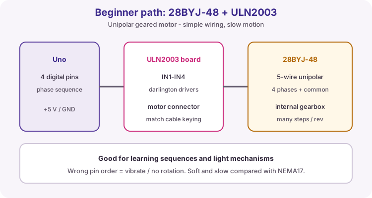
The 28BYJ-48 is a small geared unipolar stepper (five wires: four phases plus a common). A ULN2003 driver board accepts four Uno digital pins and sequences the coils. It is slow and soft, but excellent for learning step patterns and light mechanisms.
Pin order matters. Wrong phase order often vibrates or refuses to turn. Use the keyed cable orientation the board expects.
A4988 path: STEP and DIR
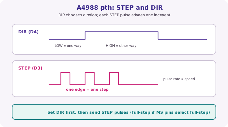
Bipolar drivers such as A4988 or DRV8825 take STEP and DIR logic from the Uno. Set DIR for the desired direction, then pulse STEP. Each rising edge advances one full step or one microstep, depending on the MS1/MS2/MS3 mode jumpers.
The worked sketch on this page is written for that STEP/DIR style. Pulse rate controls speed; total pulse count controls distance.
const byte stepPin = 3;
const byte dirPin = 4;

void moveSteps(long steps, bool clockwise) {
  digitalWrite(dirPin, clockwise ? HIGH : LOW);
  for (long i = 0; i < steps; i++) {
    digitalWrite(stepPin, HIGH);
    delayMicroseconds(800);
    digitalWrite(stepPin, LOW);
    delayMicroseconds(800);
  }
}
Power, coils and current limit
Motor current comes from VMOT on an external supply, not from the Uno. Join grounds. Fit the capacitor recommended by the module close to VMOT.
Identify coil pairs (often by resistance / continuity) and wire them to 1A/1B and 2A/2B. Set the driver's current limit (Vref pot) before the first run to protect the motor and the module. Never connect or disconnect the motor while the driver is powered.
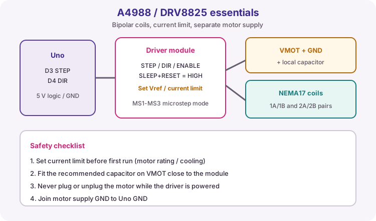
| Connection | Course practice |
|---|---|
| STEP | D3 |
| DIR | D4 |
| SLEEP / RESET | Held HIGH as module docs require |
| VMOT / GND | Motor supply + local capacitor |
| Logic VDD / GND | 5 V and common GND |
| Coils | 1A/1B and 2A/2B pairs |
Torque, speed and acceleration
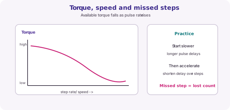
Available torque falls as step rate rises. Starting at a high pulse rate under load causes missed steps. For heavier mechanisms, start with longer delays and shorten them over the first many steps (acceleration). That is this lesson's extension challenge.
Wiring and safe build sequence
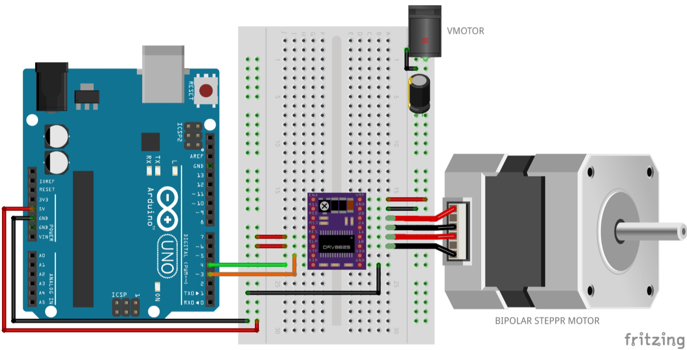
- A4988 STEP -> D3 and DIR -> D4
- RESET and SLEEP held HIGH as module documentation specifies
- VMOT and GND -> motor supply with local capacitor
- Logic VDD -> 5 V, logic GND -> common GND
- Motor coils -> 1A/1B and 2A/2B
Worked sketch
Download .ino sketchconst byte stepPin = 3;
const byte dirPin = 4;
void moveSteps(long steps, bool clockwise) {
digitalWrite(dirPin, clockwise ? HIGH : LOW);
for (long i = 0; i < steps; i++) {
digitalWrite(stepPin, HIGH);
delayMicroseconds(800);
digitalWrite(stepPin, LOW);
delayMicroseconds(800);
}
}
void setup() {
pinMode(stepPin, OUTPUT);
pinMode(dirPin, OUTPUT);
}
void loop() {
moveSteps(200, true);
delay(500);
moveSteps(200, false);
delay(500);
}How the code works
- One pulse advances one full step only when microstep pins select full-step mode.
- 200 steps is one revolution for a common 1.8-degree motor, not for every motor/gearbox.
- If you use a 28BYJ-48 instead, drive four phase pins in sequence - the STEP/DIR sketch will not match that wiring.
Test and record evidence
Practical evidence checklist
Common faults and checks
- Identify coil pairs with resistance/continuity measurements.
- Jerking without rotation suggests wrong coil pairing.
- Never plug/unplug a motor while the driver is powered.
- If it stalls or skips, slow the pulse rate and check the current limit.
Check your understanding
Q1. Why can a stepper lose position?
Show answer
Open-loop steps may be missed if load or speed exceeds available torque.
Q2. What must be set on an A4988?
Show answer
Its current limit, appropriate to the motor and module cooling.
Q3. What does one STEP pulse do on an A4988?
Show answer
Advances one full step or one microstep, depending on the MS mode.
Q4. Why is the 28BYJ-48 path useful for beginners?
Show answer
Simple ULN2003 wiring and a geared motor make sequences easy to learn, though motion is slow.