
14. DC Motors & H-Bridges
Control motor direction, speed and stopping safely.
Learning outcomes
- Explain stall current, back EMF and why motors need a driver supply
- Describe how an H-bridge reverses motor current
- Use IN1/IN2 plus PWM enable for direction and speed
- Stop briefly before reversing to reduce stress
Parts and preparation
Uno, L298N/TB6612-style module, low-voltage DC motor and suitable motor supply.
Before power: inspect wiring, confirm supply voltage and ensure all connected circuits share GND.

Brushed DC motor basics
A brushed DC motor has two leads. Apply voltage one way and it turns forward; reverse the polarity and it turns the other way. Higher average voltage generally means higher speed (under similar load).
When the shaft is stopped or just starting, current can be several times the normal running current (stall / start current). The windings are inductive and the brushes make electrical noise. Never drive a motor from an Arduino I/O pin - use a driver and an external supply sized for stall current, with common GND.
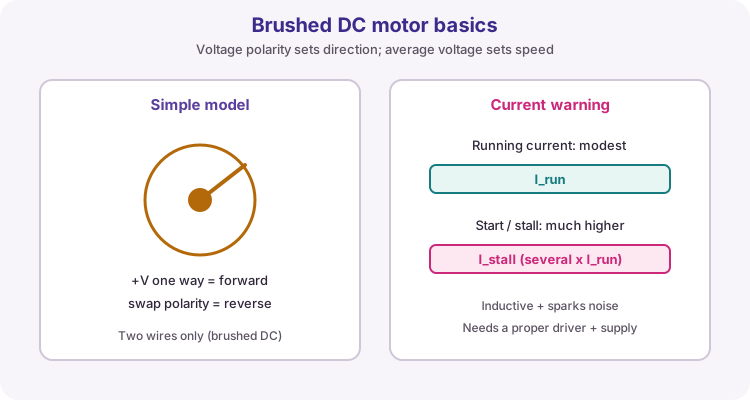
| Idea | Why it matters |
|---|---|
| Running current | Normal spinning load |
| Stall / start current | Much higher - can brown out a weak supply |
| Back EMF | Spinning motor generates voltage; sudden reverse fights that energy |
| Noise | Can upset ADC / Serial - keep wiring tidy, share GND well |
What an H-bridge does
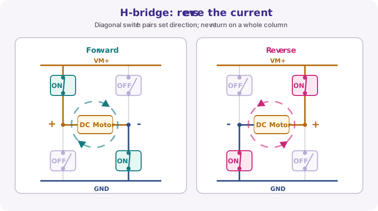
An H-bridge is four switches arranged like an H around the motor. Turning on one diagonal pair sends current left-to-right (forward). The other diagonal pair sends current the other way (reverse).
Never turn on both switches in the same vertical leg at once - that shorts the motor supply (shoot-through). Modules such as L298N or TB6612 include drivers and protection so you control logic inputs instead of bare switches.
Module pins and truth table
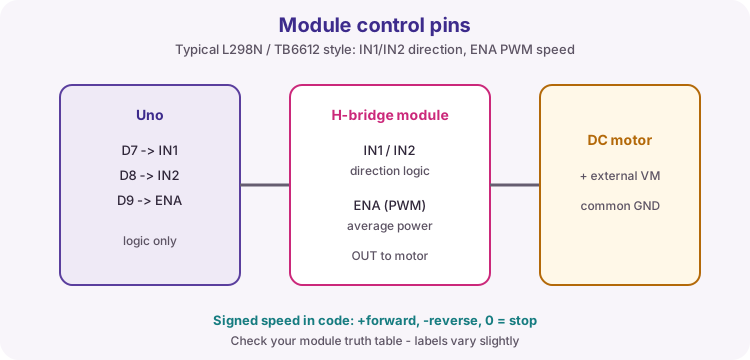
This lesson uses a typical channel: IN1 and IN2 set direction, and ENA (or PWMA) sets speed with PWM. Exact labels differ by board - always check your module silkscreen and datasheet.
| IN1 | IN2 | ENA | Typical result |
|---|---|---|---|
| HIGH | LOW | PWM / HIGH | Forward (speed from PWM) |
| LOW | HIGH | PWM / HIGH | Reverse (speed from PWM) |
| LOW | LOW | x | Coast / stop (module dependent) |
| HIGH | HIGH | x | Brake / stop (module dependent) |
PWM speed control
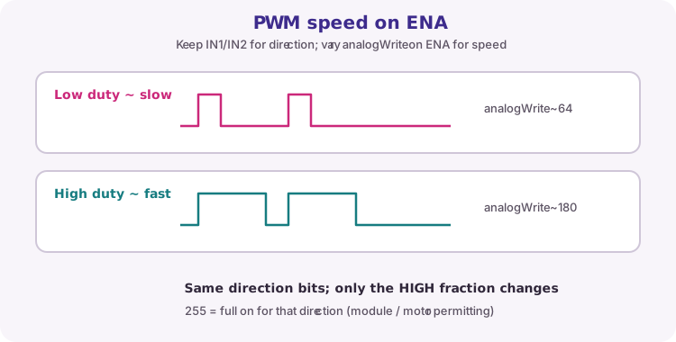
With direction bits set, analogWrite on the enable pin changes the average motor voltage. A low duty cycle runs slower; a high duty cycle runs faster. The course sketch packs direction and magnitude into one signed value: positive = forward, negative = reverse, zero = stop.
void driveMotor(int speedValue) {
  speedValue = constrain(speedValue, -255, 255);
  digitalWrite(in1, speedValue > 0);
  digitalWrite(in2, speedValue < 0);
  analogWrite(pwmPin, abs(speedValue));
}
Stop before reversing
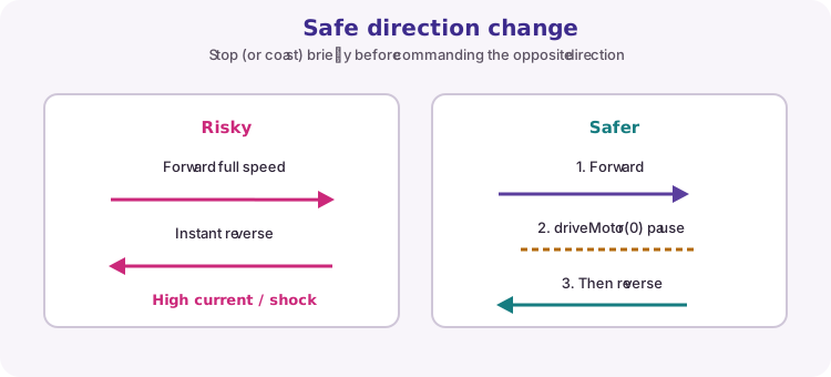
Reversing instantly while the motor is spinning hard forces a large current spike and mechanical shock. A short stop (coast or brake) lets speed fall before the opposite direction is commanded.
The worked sketch runs forward, pauses with driveMotor(0), then reverses - keep that habit in your own code.
Wiring and safe build sequence
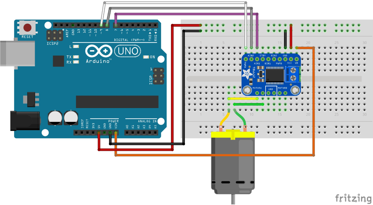
- D7 -> IN1
- D8 -> IN2
- D9/PWM -> ENA/PWMA
- Motor -> driver outputs
- Motor supply -> driver VM/GND
- Driver GND -> Uno GND
Worked sketch
Download .ino sketchconst byte in1 = 7;
const byte in2 = 8;
const byte pwmPin = 9;
void driveMotor(int speedValue) {
speedValue = constrain(speedValue, -255, 255);
digitalWrite(in1, speedValue > 0);
digitalWrite(in2, speedValue < 0);
analogWrite(pwmPin, abs(speedValue));
}
void setup() {
pinMode(in1, OUTPUT);
pinMode(in2, OUTPUT);
pinMode(pwmPin, OUTPUT);
}
void loop() {
driveMotor(180);
delay(1500);
driveMotor(0);
delay(500);
driveMotor(-180);
delay(1500);
driveMotor(0);
delay(1000);
}How the code works
- Positive/negative signed speed combines direction and magnitude.
- A stop interval reduces mechanical and electrical stress.
- If your module needs ENA jumpered HIGH for full speed tests, still prefer PWM for controllable speed.
Test and record evidence
Practical evidence checklist
Common faults and checks
- Use a motor supply able to provide stall current.
- Never power the motor from an Arduino I/O or 5 V pin.
- If only one direction works, inspect both logic inputs.
- L298N voltage drop is large - a 6 V motor may need a higher VM than you expect; TB6612 wastes less.
Check your understanding
Q1. What does an H-bridge change?
Show answer
The direction of current through the motor.
Q2. Why is stall current important when choosing a supply?
Show answer
It can be several times running current and will brown out a weak pack.
Q3. What do IN1/IN2 usually set, and what does ENA PWM set?
Show answer
Direction; average speed/power.
Q4. Why stop before reversing?
Show answer
To reduce current spikes, mechanical shock and driver stress.