
47. Deep Sleep and Power Management
Build a battery-style pulse logger: wake on a timer, read a sensor stand-in, print a line, then sleep again.
Learning outcomes
- Explain duty-cycling for battery IoT nodes
- Contrast deep sleep with always-on Wi-Fi draw
- Keep a boot count in RTC memory across sleeps
- Wake, sample an ADC reading, log it, then sleep again
- Print the wake cause to confirm timer wakes
Parts and preparation
ESP32 DevKit, USB data cable, 10 k ohm potentiometer on GPIO 34 (stand-in field sensor) for sketch 2. Sketch 1 needs USB only.
Before power: inspect wiring, confirm supply voltage and ensure all connected circuits share GND.
Project: Battery pulse logger
Field nodes often wake briefly, take one reading, log or publish, then sleep for minutes. You will build that pulse pattern with a potentiometer as the sensor stand-in.
Sketch 1 proves timer wake + RTC boot count. Sketch 2 is the logger: wake, read GPIO 34, print Boot/ADC/wake cause, sleep 5 s again.
| Mode (course level) | Rough idea |
|---|---|
| Active + WiFi | Highest draw |
| Deep sleep | Most of chip off; wake restarts setup() |
| RTC_DATA_ATTR | Survives sleep, not power cut |
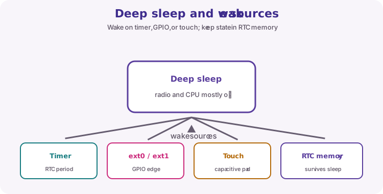
Deep sleep and wake sources
Deep sleep loses normal SRAM. Timer wake is the logger clock. EXT0/EXT1 and touch are other wake sources for later (button to wake). Always print esp_sleep_get_wakeup_cause() while learning.
| Wake source | Typical use |
|---|---|
| Timer | Sample every N seconds/minutes |
| EXT0 / EXT1 | Button or door switch |
| Touch | Capacitive pad where supported |
RTC memory versus NVS
RTC_DATA_ATTR keeps bootCount across sleeps until USB power is removed. Credentials and durable settings belong in Preferences / NVS (lesson 45 ideas), not RTC alone.
| Storage | Survives deep sleep? | Survives power cut? |
|---|---|---|
| Normal globals | No | No |
| RTC_DATA_ATTR | Yes | No |
| Preferences / NVS | Yes | Yes |
Honest current measurement
DevKit USB-UART chips and LEDs often dominate a USB current meter. Expect a qualitative drop in class, not a datasheet microamp figure.
Design pattern for a battery node
Wake -> sense quickly -> connect WiFi only if publishing -> sleep. This lesson stops before WiFi so the sleep/sample rhythm stays clear. Adding a publish step is a natural challenge after the logger works.
Wiring and safe build sequence
- Sketch 1: USB only
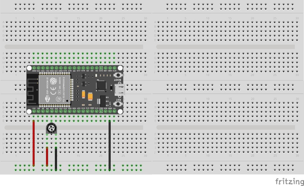
- Sketch 2: pot 3V3 -> one end, GND -> other end, wiper -> GPIO 34
- Serial Monitor 115200 before reset to catch boot lines
Worked sketch 1: Timer wake and boot count
Download .ino sketchWhat this sketch is for: Prove deep sleep: every ~5 s the board restarts setup(), bootCount rises, and wake cause becomes timer.
#include <esp_sleep.h>

RTC_DATA_ATTR int bootCount = 0;

void printWakeCause() {
  esp_sleep_wakeup_cause_t cause = esp_sleep_get_wakeup_cause();
  switch (cause) {
    case ESP_SLEEP_WAKEUP_TIMER:
      Serial.println("Wake cause: timer");
      break;
    case ESP_SLEEP_WAKEUP_EXT0:
      Serial.println("Wake cause: EXT0");
      break;
    case ESP_SLEEP_WAKEUP_EXT1:
      Serial.println("Wake cause: EXT1");
      break;
    default:
      Serial.println("Wake cause: power-on / reset / other");
      break;
  }
}

void setup() {
  Serial.begin(115200);
  delay(300);

  bootCount++;
  Serial.print("Boot #");
  Serial.println(bootCount);
  printWakeCause();
  Serial.println("Sleeping 5 seconds...");

  esp_sleep_enable_timer_wakeup(5ULL * 1000000ULL);
  esp_deep_sleep_start();
}

void loop() {
}
How the code works
- 5ULL * 1000000ULL is five seconds in microseconds.
- First boot after plug-in is usually power-on; later boots show timer.
- loop is unused - sleep restarts at setup().
Worked sketch 2: Battery pulse logger (ADC sample)
Download .ino sketchWhat this sketch is for: Useful logger behaviour: each wake reads the pot on GPIO 34, prints Boot, ADC and wake cause, then sleeps again. Turn the pot between wakes to see changing samples. Match the breadboard layout below before upload.
#include <esp_sleep.h>

RTC_DATA_ATTR int bootCount = 0;
const int sensePin = 34;

void printWakeCause() {
  esp_sleep_wakeup_cause_t cause = esp_sleep_get_wakeup_cause();
  if (cause == ESP_SLEEP_WAKEUP_TIMER) Serial.println("Wake cause: timer");
  else Serial.println("Wake cause: power-on / reset / other");
}

void setup() {
  Serial.begin(115200);
  delay(300);

  bootCount++;
  int sample = analogRead(sensePin);

  Serial.print("Boot #");
  Serial.print(bootCount);
  Serial.print("  ADC ");
  Serial.println(sample);
  printWakeCause();
  Serial.println("Pulse logged - sleeping 5 s");

  esp_sleep_enable_timer_wakeup(5ULL * 1000000ULL);
  esp_deep_sleep_start();
}

void loop() {
}
How the code works
- analogRead runs only while awake - then the chip sleeps.
- Pot on ADC1 (GPIO 34) stays valid even though WiFi is off in this sketch.
- Change the pot between wake lines to prove the logger captures new values.
- Build from the breadboard photo: pot on GPIO 34.
Test and record evidence
Practical evidence checklist
Common faults and checks
- Boot stuck at 1: power cycled or USB reopen resetting each time.
- ADC flat: pot on 3V3/GND/wiper GPIO 34.
- No Serial: open Monitor quickly at 115200.
Check your understanding
Q1. What product pattern is the pulse logger?
Show answer
Wake, sample, log, deep sleep on a timer.
Q2. Why does always-on WiFi hurt batteries?
Show answer
Radio keep-alive draws high continuous current.
Q3. What does RTC_DATA_ATTR preserve?
Show answer
A variable across deep sleep wakes (until power cut).
Q4. Where does execution continue after timer wake?
Show answer
Typically setup(), like a reset.
Q5. Does RTC survive unplugging USB?
Show answer
No.
Q6. What does sketch 2 add beyond boot count?
Show answer
An ADC sample each wake before sleeping.
Q7. Name another wake source besides timer
Show answer
EXT0/EXT1 GPIO or touch.
Q8. Why might USB meters exaggerate sleep current?
Show answer
DevKit UART chips and LEDs often stay on.