
36. 3.3 V Logic, Power Rails and Level Shifting
Protect ESP32 GPIO and build a safe front-panel acknowledge button with a status LED - never feed 5 V into pins.
Learning outcomes
- State why 5 V must never be applied to ESP32 GPIO
- Identify USB, VIN and 3V3 rails on a typical DevKit
- Design a two-resistor divider for a 5 V digital echo into 3.3 V logic
- Build a panel acknowledge button with debounce and status LED
- Describe when a MOSFET bidirectional shifter beats a divider
Parts and preparation
ESP32 DevKit, USB data cable, push-button, LED + 220-330 ohm resistor, jumper wires. Optional: two resistors (e.g. 2.2 k ohm and 3.3 k ohm) for a 5 V echo divider demo; optional HC-SR04.
Before power: inspect wiring, confirm supply voltage and ensure all connected circuits share GND.
Project: Safe panel acknowledge
Build a 3.3 V-safe front-panel control: press to acknowledge / arm a status LED. That is the same habit you need on any ESP32 machine panel - buttons to GND with INPUT_PULLUP, no 5 V on GPIO, modest LED current.
Sketch 1 proves the button and prints the 3.3 V rule. Sketch 2 is the useful panel: edge-detect press, debounce with millis, toggle a status LED on GPIO 2.
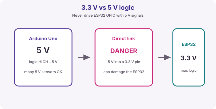
Never put 5 V into ESP32 GPIO
ESP32 pins are 3.3 V logic. A 5 V signal from an Uno or many sensor modules can damage the pin. If a module outputs 5 V on a data line, add level shifting or use a 3.3 V-safe variant.
USB, VIN and 3V3 rails
USB powers most DevKits. VIN/5V may accept external 5 V within board limits. 3V3 feeds the ESP32 and 3.3 V peripherals. Do not inject 5 V into 3V3. Do not draw strip/motor current from the tiny regulator. Share GND.
| Rail / path | Typical use |
|---|---|
| USB 5 V | Power the DevKit from the PC |
| VIN / 5V header | External 5 V input if the board allows it |
| 3V3 | ESP32 core and 3.3 V logic devices |
| GND | Common return - always share with sensors |
Voltage divider for a 5 V sensor echo
HC-SR04 Echo is about 5 V - use a divider before ESP32 GPIO. Course example: R1 = 2.2 k ohm from Echo, R2 = 3.3 k ohm to GND, mid-point to GPIO. Vout = Vin * R2 / (R1 + R2) -> about 3.0 V from 5 V. Trig can often stay 3.3 V from ESP32.
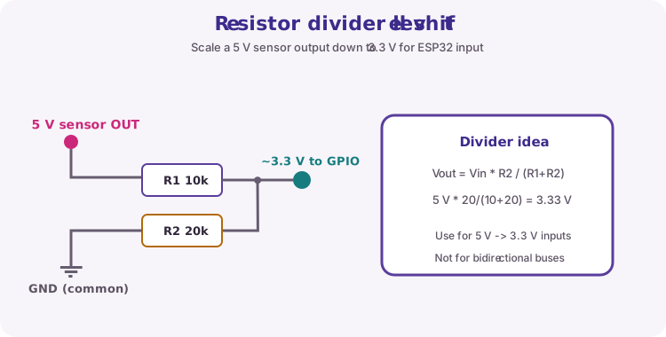
// Vout = Vin * R2 / (R1 + R2)
// Example: 5 V * 3.3k / (2.2k + 3.3k) = 3.0 V
MOSFET bidirectional shifters
Dividers are fine for one-way 5 V -> 3.3 V inputs. For I2C or bidirectional lines use a proper MOSFET shifter module.
GPIO 0 caution; this lesson uses GPIO 4
GPIO 0 is a strapping pin. A button to GND there can confuse boot. Use GPIO 4 with INPUT_PULLUP for the panel button.
Wiring and safe build sequence
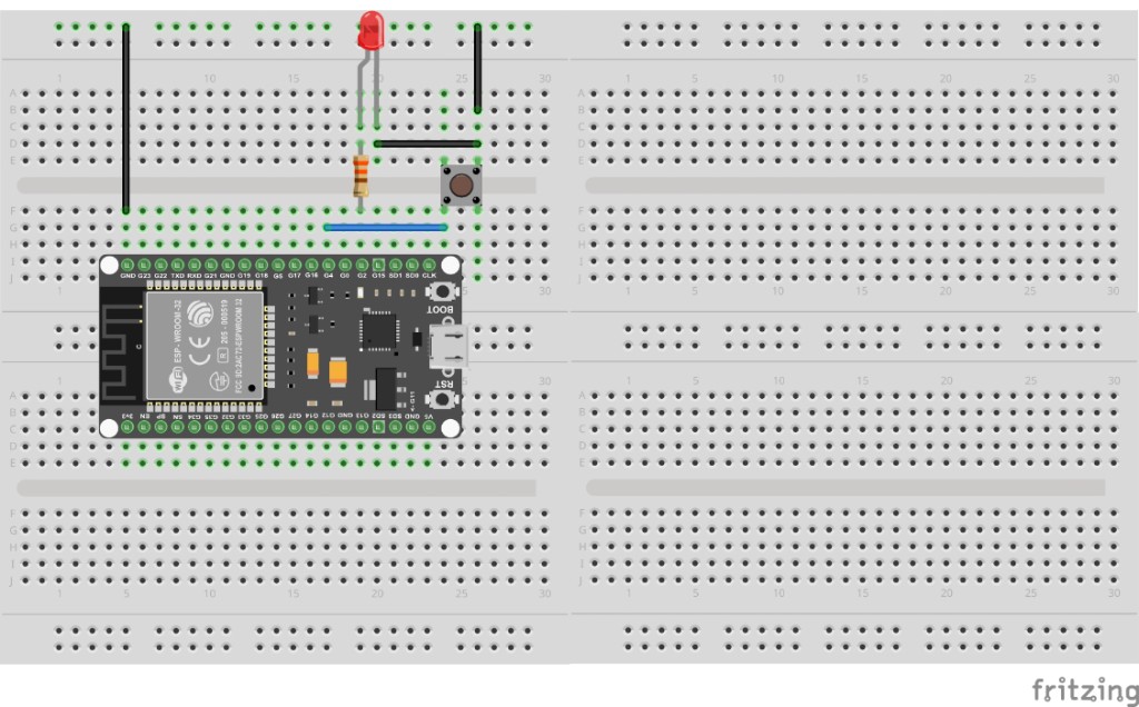
- ESP32 GPIO 4 -> one side of push-button; other side -> GND
- Sketch 2: GPIO 2 -> 220-330 ohm -> LED anode; cathode -> GND (or on-board LED)
- USB power; Serial Monitor 115200
- Optional HC-SR04 divider on Echo as described in theory
Worked sketch 1: Safe button read
Download .ino sketchWhat this sketch is for: Discovery: INPUT_PULLUP button on GPIO 4 prints pressed/open and reminds you ESP32 is 3.3 V logic.
const int btnPin = 4;

void setup() {
  pinMode(btnPin, INPUT_PULLUP);
  Serial.begin(115200);
  delay(300);
  Serial.println("ESP32 is 3.3 V logic - never feed 5 V into GPIO");
}

void loop() {
  int pressed = (digitalRead(btnPin) == LOW);
  Serial.println(pressed ? "button pressed" : "button open");
  delay(200);
}
How the code works
- INPUT_PULLUP: idle HIGH; press to GND reads LOW.
- GPIO 4 avoids the GPIO 0 boot-strap hazard.
Worked sketch 2: Panel acknowledge with status LED
Download .ino sketchWhat this sketch is for: Useful panel control: each clean button edge toggles a status LED (armed/acknowledged). millis debounce stops bounce from flipping twice. Match the breadboard layout below before upload.
const int btnPin = 4;
const int ledPin = 2;
const unsigned long debounceMs = 40;

bool ledOn = false;
bool lastStable = HIGH;
bool lastRead = HIGH;
unsigned long lastEdge = 0;

void setup() {
  pinMode(btnPin, INPUT_PULLUP);
  pinMode(ledPin, OUTPUT);
  digitalWrite(ledPin, LOW);
  Serial.begin(115200);
  Serial.println("Panel ACK - press to toggle status LED");
}

void loop() {
  bool reading = digitalRead(btnPin);
  if (reading != lastRead) {
    lastEdge = millis();
    lastRead = reading;
  }

  if ((millis() - lastEdge) > debounceMs && reading != lastStable) {
    lastStable = reading;
    if (lastStable == LOW) {
      ledOn = !ledOn;
      digitalWrite(ledPin, ledOn ? HIGH : LOW);
      Serial.println(ledOn ? "ACK / armed" : "cleared");
    }
  }
}
How the code works
- Toggle only on the press edge (HIGH to LOW), not while held.
- debounceMs filters mechanical bounce.
- Same 3.3 V button habit scales to larger control panels.
- Build from the breadboard photo: GPIO 4 button, GPIO 2 LED + resistor.
Test and record evidence
Practical evidence checklist
Common faults and checks
- Always open: button legs and common GND.
- Double toggles: increase debounceMs slightly.
- GPIO 0 mistakes: keep the button on GPIO 4 for this lab.
- HC-SR04: verify divider mid-point before connecting Echo to ESP32.
Check your understanding
Q1. What project is sketch 2?
Show answer
A safe front-panel acknowledge button with status LED.
Q2. What voltage class are ESP32 GPIO pins?
Show answer
3.3 V - do not apply 5 V.
Q3. What must you share with every sensor?
Show answer
GND.
Q4. Divider formula?
Show answer
Vout = Vin * R2 / (R1 + R2).
Q5. Why avoid GPIO 0 for the button?
Show answer
Strapping/boot pin - can disturb boot or download.
Q6. When is a MOSFET shifter better?
Show answer
Bidirectional or open-drain buses such as I2C.
Q7. Why debounce the panel button?
Show answer
Mechanical bounce can create false extra edges.