
25. Practical Fault-Finding & Multimeter Skills
Diagnose circuits methodically instead of guessing.
Learning outcomes
- Set up a digital multimeter safely for DC voltage, continuity and resistance
- Apply a power, then signal, then software fault sequence without guessing
- Predict and measure expected HIGH/LOW and 5 V rail readings on an Uno
- Isolate a project into subsystems and prove each with a minimal test
- Keep an evidence-based fault log suitable for college practical work
Parts and preparation
Arduino Uno, USB data cable, digital multimeter with probes, breadboard, red LED, 330 ohm resistor, push-button (optional), jumper wires, and one previously built circuit or module to diagnose.
Before power: inspect wiring, confirm supply voltage and ensure all connected circuits share GND.
Why method beats guessing
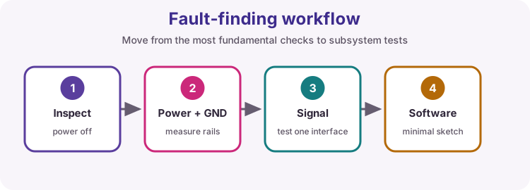
Random rewiring wastes time and can create new faults. College practical work expects a repeatable process: state the symptom, remove power, inspect, measure, change one thing, then re-test.
Most Arduino faults fall into three layers: power/ground, wiring/signals, then software. Check them in that order. Uploading a fixed sketch while the 5 V rail is dead teaches nothing.
Fault-finding sequence
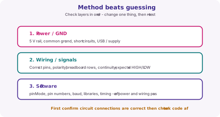
Use this order every time. Tick each step in your logbook before moving on.
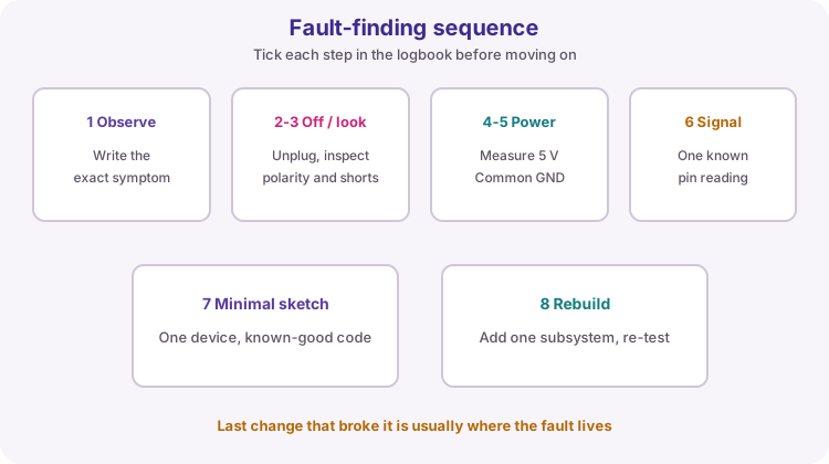
| Step | Action | Pass looks like |
|---|---|---|
| 1. Observe | Write the exact symptom (what works, what does not, when) | Clear one-sentence problem statement |
| 2. Power off | Unplug USB / VIN before moving wires or using continuity | Board fully unpowered |
| 3. Inspect | Check polarity, breadboard rows, loose jumpers, shorts, correct pins | No obvious wiring errors |
| 4. Power / GND | Power on; measure 5 V to GND; confirm ON LED if present | About 4.8-5.2 V on the 5 V pin |
| 5. Common GND | Confirm every module shares GND with the Uno | Continuity (power off) or 0 V difference where expected |
| 6. One signal | Measure one known input or output under a controlled sketch | Reading matches HIGH/LOW or expected analogue band |
| 7. Minimal sketch | Test one device alone with the smallest known-good code | That device works in isolation |
| 8. Rebuild | Add subsystems one at a time; re-test after each | Fault isolated to the last change |
Multimeter setup and safety
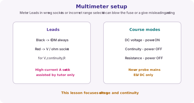
A digital multimeter (DMM) is your main tool for proving electrical claims. Wrong range or wrong socket can blow the meter fuse or give nonsense readings.
Before every session: inspect probe tips, confirm the black lead is in COM, and put the red lead in the V/ohm socket for voltage, continuity and resistance. Use the dedicated high-current socket only when measuring current in series - and only if your tutor asks for it. This course focuses on voltage and continuity.
| Mode | When to use | Power on circuit? | Notes |
|---|---|---|---|
| DC voltage | Rails, pin HIGH/LOW, sensor divider voltage | Yes | Black on GND; red on the point under test |
| Continuity (beep) | Prove a wire/row connects two points | No - power off | Beep means low resistance path |
| Resistance (ohm) | Check a resistor or open path (careful) | No - power off | Remove or isolate the part if readings look odd |
| AC voltage | Not used in this ELV DC course | - | Do not probe mains |
| Current (A) | Advanced / tutor-led only | Yes, meter in series | Wrong connection can short the supply |
How to measure DC voltage on an Uno
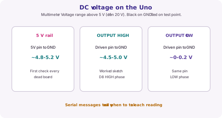
Set the meter to a DC range above 5 V (often 20 V). Black probe to Uno GND. Red probe to the test point.
Expected readings on a healthy Uno R3 (USB powered):
| Test point | Typical reading | If wrong, check |
|---|---|---|
| 5V pin to GND | About 4.8-5.2 V | USB cable, port, board power LED, short on 5 V rail |
| 3.3V pin to GND | About 3.2-3.4 V | Regulator / board damage (less used in early labs) |
| Digital OUTPUT HIGH to GND | About 4.5-5.0 V | pinMode OUTPUT, correct pin, series load not shorting to GND |
| Digital OUTPUT LOW to GND | About 0-0.2 V | Code stuck HIGH; short to 5 V; wrong pin |
| INPUT_PULLUP open button pin | Near 5 V | Missing INPUT_PULLUP; wire floating |
| INPUT_PULLUP pressed to GND | Near 0 V | Button not to GND; wrong pin |
| Pot wiper (A0) mid-travel | Roughly mid-rail (varies) | Missing 5 V/GND on pot ends; wiper not on A0 |
Continuity and resistance (power off)
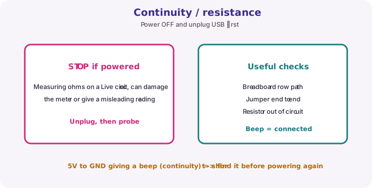
Switch power off and unplug USB before continuity or resistance tests. Measuring resistance on a live circuit can damage the meter and produce false values.
Useful checks: breadboard row continuity, jumper end-to-end, resistor value (330 ohm should read near 330 ohm out of circuit), and that two nets that should be separate are not shorted.
Symptom to likely cause
Match what you see to a first measurement before changing lots of wires.
| Symptom | Likely cause | First check |
|---|---|---|
| Board dead / no power LED | USB/cable/port or short on 5 V | Measure 5 V to GND; try known-good data cable |
| Uploads but nothing happens | Wrong pin, missing GND, dead breadboard row | Continuity to the device; voltage on the driven pin |
| LED never lights | Reversed LED, missing resistor, wrong pin | Polarity; measure pin HIGH; check resistor in series |
| LED always on / pin hot | Short, no resistor, wrong polarity drive | Power off; inspect; add series resistor; stay within pin current |
| Button random / stuck | Floating input or wrong polarity test | INPUT_PULLUP; measure open vs pressed |
| Sensor stuck at 0 or 1023 | Open wire or rail short on divider | Measure divider mid-point voltage; confirm 5 V and GND |
| Motor resets the board | Motor current from USB/pin alone | External motor supply + common GND + driver |
| Serial garbage / silent | Baud mismatch or charge-only cable | Match baud; TX/RX LEDs; data cable |
| Works alone, fails when combined | Pin clash, shared bus conflict, power droop | Minimal tests; one module at a time; measure 5 V under load |
Minimal test strategy
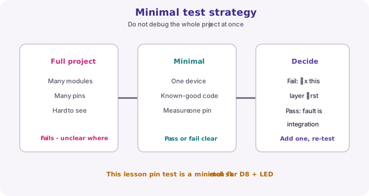
When a full project fails, do not debug everything at once. Unplug unrelated modules. Load the smallest sketch that only exercises the suspect part (this lesson's pin HIGH/LOW test, Blink, or a single-sensor Serial print).
If the minimal test passes, the device and basic wiring are fine - the fault is in integration (wrong pin define, shared pin, library conflict, timing, or power under load). If the minimal test fails, fix that layer before reconnecting the rest.
Practical evidence and logbook
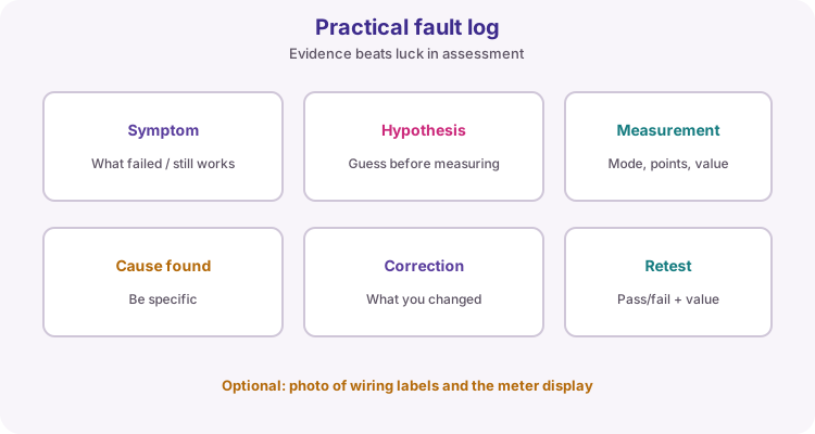
Assessment marks depend on evidence, not luck. For each fault session record:
| Log field | What to write |
|---|---|
| Circuit / version | Lesson or project name and date |
| Symptom | What failed, and what still worked |
| Hypothesis | What you thought was wrong before measuring |
| Measurement | Meter mode, points probed, value read |
| Cause found | The actual fault (be specific) |
| Correction | What you changed |
| Retest result | Pass/fail with a measured value if relevant |
| Photo (optional) | Clear shot of wiring labels and the meter display |
Wiring and safe build sequence
- Build a known-good LED test: Uno D8 -> 330 ohm -> LED anode; LED cathode -> GND
- Set multimeter to DC volts; black probe on Uno GND; confirm about 5 V on the 5 V pin
- Upload the worked sketch; measure D8 to GND during the HIGH message (about 5 V) and LOW message (about 0 V)
- Power off; set continuity; confirm D8 jumper continuity to the resistor row and cathode path to GND
- Optional: add an INPUT_PULLUP button from D2 to GND; measure open (about 5 V) and pressed (about 0 V)
- Then diagnose a completed earlier project using the full sequence and log each step
Worked sketch
Download .ino sketchconst int TEST_PIN = 8;
void setup() {
pinMode(TEST_PIN, OUTPUT);
Serial.begin(9600);
Serial.println("Fault-finding pin test");
Serial.println("Measure TEST_PIN to GND with meter on DC volts");
}
void loop() {
digitalWrite(TEST_PIN, HIGH);
Serial.println("HIGH - expect about 5 V on pin 8");
delay(3000);
digitalWrite(TEST_PIN, LOW);
Serial.println("LOW - expect about 0 V on pin 8");
delay(3000);
}How the code works
- TEST_PIN is a named constant so the driven pin is obvious in wiring and in the logbook.
- Serial messages tell you when to take each meter reading so software and measurement stay in sync.
- If Serial is silent but the pin still toggles, you can still measure; fix USB/baud separately.
Test and record evidence
Practical evidence checklist
Common faults and checks
- No 5 V on the 5 V pin: fix USB/power before any signal tests.
- Pin stays near 0 V on HIGH: wrong pin number, pin not set OUTPUT, or short to GND.
- Pin near 5 V but LED dark: reversed LED, open breadboard row, or missing series resistor path.
- Continuity always beeps between 5 V and GND: short - power off and find the bridge before powering again.
- Readings jump wildly: poor probe contact, wrong meter range, or floating probe (keep black on GND).
Check your understanding
Q1. In what order should you usually investigate an Arduino fault?
Show answer
Power and ground first, then wiring/signals, then software.
Q2. Can you measure continuity with the Uno still powered from USB?
Show answer
No. Remove power first.
Q3. Black probe on GND, red on a digital OUTPUT driven HIGH - roughly what should you read?
Show answer
About 5 V on a 5 V Uno.
Q4. Why use a minimal sketch when a big project fails?
Show answer
It separates a single device/wiring fault from integration and software interaction faults.
Q5. Name three fields that belong in a practical fault log.
Show answer
Examples: symptom, measurement, cause found, correction, retest result.