
29. Interrupts on the Uno
Use Uno interrupts and sleep: external, pin-change, timer, USART, ADC, comparator, watchdog, and power-down wake.
Learning outcomes
- Explain why an ISR must stay short and use volatile shared data
- Use attachInterrupt on D2/D3 with the correct trigger mode
- Enable a pin-change interrupt on another digital pin
- Set up a Timer1 compare-match interrupt for a steady tick
- Recognise USART, ADC, comparator and watchdog interrupt templates
- Put the Uno into power-down sleep and wake it with an interrupt without restarting setup()
Parts and preparation
Uno, push-button, LED with 330 ohm resistor and a passive buzzer. Serial Monitor for the USART example.
Before power: inspect wiring, confirm supply voltage and ensure all connected circuits share GND.
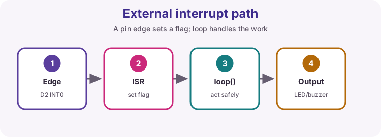
What an interrupt does
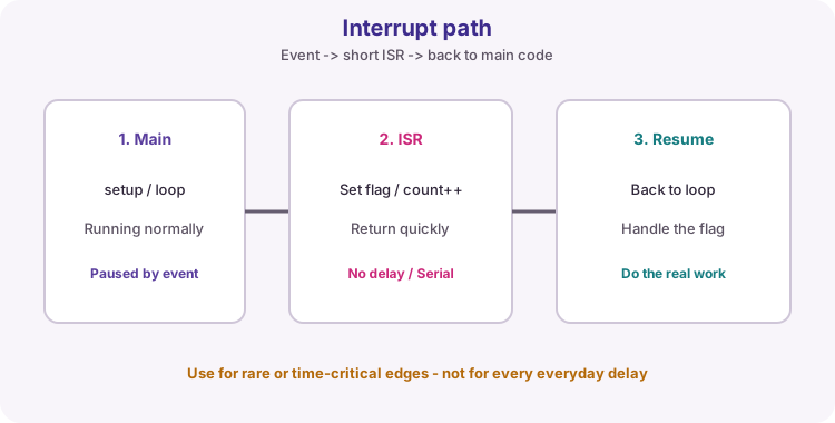
An interrupt pauses the main program when a hardware event happens, runs an ISR (interrupt service routine), then returns. Use interrupts for rare or time-critical edges: buttons, encoders, UART bytes, timer ticks.
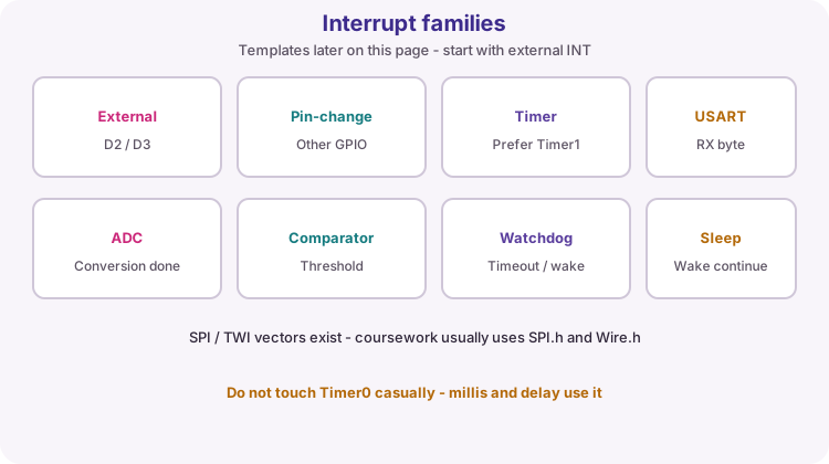
On the ATmega328P Uno you will meet several interrupt families. The worked sketch at the bottom uses an external interrupt; the sections below give a short template for each family.
Interrupt families at a glance
This page is a map plus templates. Start with external INT0/INT1 for the practical, then skim the other families so datasheet names look familiar.
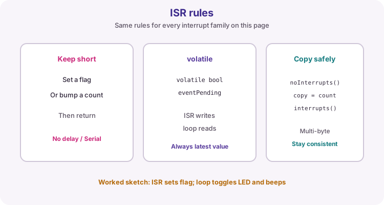
ISR rules (all interrupt types)
Keep every ISR extremely short: set a flag or bump a count, then return. Do not call delay, Serial, floating-point maths or long library routines inside an ISR.
Any variable written in an ISR and read in loop must be volatile. For multi-byte values that must stay consistent, briefly disable interrupts while you copy them in loop:
volatile unsigned int eventCount = 0;

void loop() {
  noInterrupts();
  unsigned int countCopy = eventCount;
  interrupts();
}
External interrupt (INT0 / INT1)
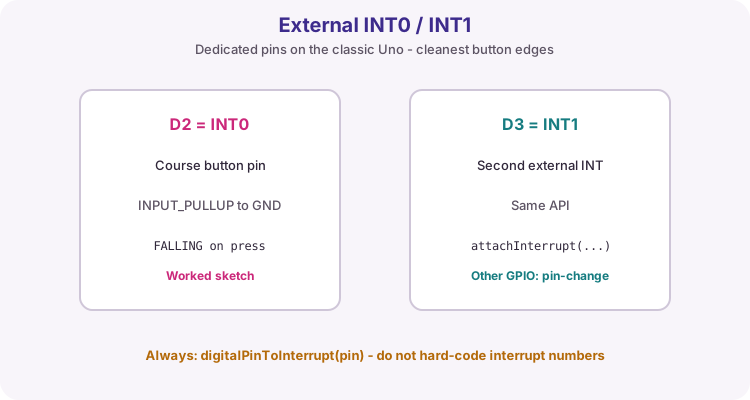
The classic Uno has two dedicated external interrupt pins: INT0 on D2 and INT1 on D3. Use attachInterrupt for these. Always map the pin with digitalPinToInterrupt so the same sketch stays clearer on other boards.
Template: INPUT_PULLUP button to GND on D2, FALLING edge sets a flag. Finish the work in loop.
const byte buttonPin = 2;

volatile bool eventPending = false;

void onButtonEdge() {
  eventPending = true;
}

void setup() {
  pinMode(buttonPin, INPUT_PULLUP);
  Serial.begin(9600);
  attachInterrupt(digitalPinToInterrupt(buttonPin), onButtonEdge, FALLING);
}

void loop() {
  if (eventPending) {
    eventPending = false;
    Serial.println("Edge");
  }
}
External trigger modes
The last argument to attachInterrupt selects when the ISR runs. With INPUT_PULLUP to GND, FALLING is the usual button press. Swap only the mode constant in the template above.
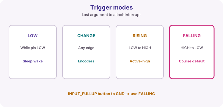
| Mode | Fires when | Typical use |
|---|---|---|
| LOW | Pin stays LOW | Level detect (can fire repeatedly while held) |
| CHANGE | Any edge HIGH/LOW | Toggle / encoder style edges |
| RISING | LOW to HIGH | Active-high pulse start |
| FALLING | HIGH to LOW | INPUT_PULLUP button to GND |
attachInterrupt(digitalPinToInterrupt(buttonPin), onButtonEdge, CHANGE);Flag in ISR, work in loop
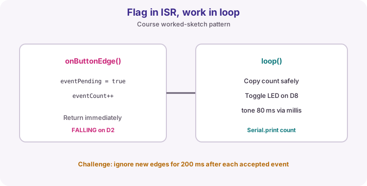
The worked sketch follows the same pattern as the small template: the ISR only sets eventPending and increments eventCount. loop copies the count under noInterrupts, toggles an LED, starts a short tone, and prints. The beep ends later with millis - never with delay inside the ISR.
Pin-change interrupt
Pin-change interrupts watch groups of pins, not only D2/D3. On the Uno: PCINT0 group covers D8-D13, PCINT1 covers A0-A5, PCINT2 covers D0-D7.
You enable a group in PCICR and the pin mask in PCMSKx. The ISR does not tell you which pin changed - read the pin in loop if you need that.
Template: watch D8 (PCINT0).
volatile bool edgePending = false;

ISR(PCINT0_vect) {
  edgePending = true;
}

void setup() {
  pinMode(8, INPUT_PULLUP);
  PCICR |= (1 << PCIE0);
  PCMSK0 |= (1 << PCINT0);
  Serial.begin(9600);
}

void loop() {
  if (edgePending) {
    edgePending = false;
    Serial.println("Pin change on Port B");
  }
}
Timer interrupt
Timer interrupts fire from Timer0, Timer1 or Timer2 on overflow or compare-match. Arduino already uses Timer0 for millis() and delay(), so prefer Timer1 for your own ticks.
Template: Timer1 CTC at about 1 Hz (16 MHz clock, /1024 prescale, OCR1A = 15624). Toggle the built-in LED from loop.
volatile bool tickPending = false;

ISR(TIMER1_COMPA_vect) {
  tickPending = true;
}

void setup() {
  pinMode(LED_BUILTIN, OUTPUT);

  noInterrupts();
  TCCR1A = 0;
  TCCR1B = 0;
  TCNT1 = 0;
  OCR1A = 15624;
  TCCR1B |= (1 << WGM12);
  TCCR1B |= (1 << CS12) | (1 << CS10);
  TIMSK1 |= (1 << OCIE1A);
  interrupts();
}

void loop() {
  if (tickPending) {
    tickPending = false;
    digitalWrite(LED_BUILTIN, !digitalRead(LED_BUILTIN));
  }
}
USART receive interrupt
The UART can interrupt when a byte arrives. Do not mix this template with Serial.begin / Serial.read on the same USART - they share the hardware.
Template: 9600 baud on the Uno USB-serial port. Send '1' or '0' from a terminal to drive LED_BUILTIN.
volatile char lastChar = 0;
volatile bool charPending = false;

ISR(USART_RX_vect) {
  lastChar = UDR0;
  charPending = true;
}

void setup() {
  pinMode(LED_BUILTIN, OUTPUT);
  UBRR0H = 0;
  UBRR0L = 103;
  UCSR0B = (1 << RXEN0) | (1 << RXCIE0);
  UCSR0C = (1 << UCSZ01) | (1 << UCSZ00);
}

void loop() {
  if (charPending) {
    noInterrupts();
    char c = lastChar;
    charPending = false;
    interrupts();
    digitalWrite(LED_BUILTIN, c == '1');
  }
}
ADC conversion interrupt
The ADC can interrupt when a conversion finishes instead of waiting in analogRead(). Start a conversion, handle the result in the ISR or in loop via a flag.
Template: free-running style start on A0; print the result from loop.
volatile int adcValue = 0;
volatile bool adcReady = false;

ISR(ADC_vect) {
  adcValue = ADC;
  adcReady = true;
}

void setup() {
  Serial.begin(9600);
  ADMUX = (1 << REFS0);
  ADCSRA = (1 << ADEN) | (1 << ADIE) | (1 << ADPS2) | (1 << ADPS1) | (1 << ADPS0);
  ADCSRA |= (1 << ADSC);
}

void loop() {
  if (adcReady) {
    noInterrupts();
    int value = adcValue;
    adcReady = false;
    interrupts();
    Serial.println(value);
    ADCSRA |= (1 << ADSC);
  }
}
Analog comparator interrupt
The analog comparator watches AIN0 (D6) against AIN1 (D7) by default, or against the bandgap / ADC mux depending on registers. It can interrupt on a compare-match change.
Template: enable the comparator interrupt and print when the output toggles. Keep wiring at safe 0-5 V levels only.
volatile bool comparePending = false;

ISR(ANALOG_COMP_vect) {
  comparePending = true;
}

void setup() {
  Serial.begin(9600);
  ADCSRB &= ~(1 << ACME);
  ACSR = (1 << ACIE);
}

void loop() {
  if (comparePending) {
    comparePending = false;
    Serial.println("Comparator change");
  }
}
Watchdog interrupt
The watchdog timer can reset the MCU or raise an interrupt. Interrupt mode is useful for a timed wake or a fail-safe tick when loop has stalled.
Template: about 1 s watchdog interrupt (WDP bits). Clear the flag in loop. Reset WDT carefully in real projects so a hung loop still recovers.
#include <avr/wdt.h>

volatile bool wdtPending = false;

ISR(WDT_vect) {
  wdtPending = true;
}

void setup() {
  Serial.begin(9600);
  noInterrupts();
  MCUSR &= ~(1 << WDRF);
  WDTCSR |= (1 << WDCE) | (1 << WDE);
  WDTCSR = (1 << WDIE) | (1 << WDP2) | (1 << WDP1);
  interrupts();
}

void loop() {
  if (wdtPending) {
    wdtPending = false;
    Serial.println("Watchdog tick");
  }
}
Sleep and wake on the Uno
The Uno (ATmega328P) does not have an ESP32-style deepSleep() API. You choose a sleep mode with set_sleep_mode() from avr/sleep.h, then call sleep_cpu(). The two modes students use most:
IDLE - lightest sleep. The CPU stops but timers and many peripherals keep running. millis() still advances. Almost any interrupt can wake the chip.
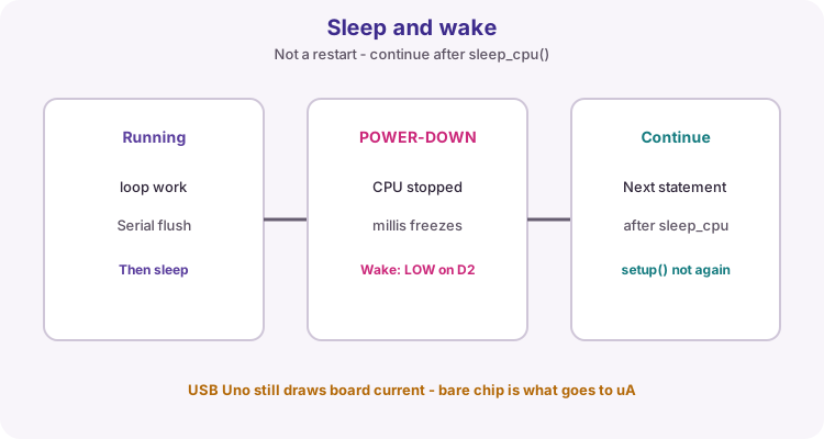
POWER-DOWN - deepest sleep on the Uno (the closest thing to deep sleep). Most clocks stop to save power. Timer0 stops, so millis() freezes until you wake. Only selected wake sources work (see the table).
What happens on wake: the sketch does not restart. setup() does not run again. Execution continues at the next statement after sleep_cpu(). RAM and most register state stay intact. Only a real reset (power cycle, reset button, brown-out, or watchdog reset mode) starts the program from the beginning again.
Important for POWER-DOWN: dedicated external INT0/INT1 wake best as LOW level (not FALLING/RISING). Pin-change and watchdog interrupt mode can also wake from POWER-DOWN. Template: button on D2 to GND with INPUT_PULLUP; sleep until the pin is held LOW.
| Sleep mode | Depth | Typical wake sources |
|---|---|---|
| SLEEP_MODE_IDLE | Light | Almost any interrupt (timer, USART, external, pin-change, ...) |
| SLEEP_MODE_ADC | Light-medium | ADC complete; some other interrupts |
| SLEEP_MODE_PWR_SAVE | Deeper | Timer2 async, external/pin-change, watchdog, TWI address match |
| SLEEP_MODE_STANDBY | Deep (osc. on) | Similar to power-down but faster wake |
| SLEEP_MODE_PWR_DOWN | Deepest | External INT as LOW, pin-change, watchdog interrupt, TWI address match |
#include <avr/sleep.h>

const byte wakePin = 2;

void wakeISR() {
}

void enterPowerDown() {
  set_sleep_mode(SLEEP_MODE_PWR_DOWN);
  sleep_enable();
  attachInterrupt(digitalPinToInterrupt(wakePin), wakeISR, LOW);
  sleep_cpu();
  sleep_disable();
  detachInterrupt(digitalPinToInterrupt(wakePin));
}

void setup() {
  pinMode(wakePin, INPUT_PULLUP);
  pinMode(LED_BUILTIN, OUTPUT);
  Serial.begin(9600);
  delay(100);
  Serial.println("Running");
}

void loop() {
  Serial.println("Sleeping");
  Serial.flush();
  digitalWrite(LED_BUILTIN, LOW);

  enterPowerDown();

  digitalWrite(LED_BUILTIN, HIGH);
  Serial.println("Woke - continued after sleep_cpu()");
  delay(500);
}
Typical current draw (board vs chip)
Sleep only cuts MCU core current. On a USB Uno board the USB-serial chip, regulators and LEDs still draw tens of milliamps, so POWER-DOWN barely changes what you measure at the USB cable. On a bare ATmega328P (minimal 3.3 V/5 V circuit, BOD off where allowed) the same modes drop into the microamp range.
Figures below are typical order-of-magnitude values for teaching, not a guarantee for every board revision.
| Mode | UNO development board (typical) | ATmega328P chip alone (typical) |
|---|---|---|
| Normal active run | about 45 mA to 50 mA | about 12 mA to 15 mA |
| Idle sleep | about 30 mA to 35 mA | about 1.0 mA to 1.5 mA |
| Power-down (deepest sleep) | about 30 mA to 35 mA | about 0.1 uA to 0.5 uA (BOD off) |
SPI and TWI (I2C) interrupts
The Uno also has SPI and TWI (I2C) interrupt vectors. In Arduino sketches you almost always use the SPI and Wire libraries instead of writing these ISRs yourself.
Know they exist for datasheet reading; prefer the libraries for coursework unless a brief specifically asks for register-level SPI/TWI interrupts.
| Source | Vector (typical) | Course approach |
|---|---|---|
| SPI | SPI_STC_vect | Use SPI.h unless told otherwise |
| TWI / I2C | TWI_vect | Use Wire.h unless told otherwise |
Interrupt map at a glance
Quick map of the families covered on this page for Uno / ATmega328P coursework.
| Family | How you enable it | Best for |
|---|---|---|
| External INT0/INT1 | attachInterrupt on D2/D3 | Clean button / limit edges |
| Pin-change | PCICR + PCMSKx + ISR(PCINTx_vect) | Other GPIO pins |
| Timer | TCCRx / TIMSKx + ISR(TIMERn_...) | Steady ticks without delay |
| USART RX | UCSR0B RXCIE0 + ISR(USART_RX_vect) | Byte-by-byte serial input |
| ADC | ADCSRA ADIE + ISR(ADC_vect) | Non-blocking analogue reads |
| Analog comparator | ACSR ACIE + ISR(ANALOG_COMP_vect) | Fast threshold detect |
| Watchdog | WDTCSR WDIE + ISR(WDT_vect) | Timeout / wake helper |
| Sleep / wake | set_sleep_mode + sleep_cpu() | Save power; continue after wake |
| SPI / TWI | Library or STC/TWI vectors | Usually SPI.h / Wire.h |
Wiring and safe build sequence
- For the worked sketch: button from D2 to GND with INPUT_PULLUP
- D8 -> 330 ohm -> LED -> GND
- Passive buzzer signal -> D7; buzzer GND -> GND
- Other templates: follow the pin named in that section (D8 for pin-change, LED_BUILTIN for timer/USART)
- Sleep template: same D2 button; hold LOW to wake from power-down
Worked sketch
Download .ino sketchconst byte buttonPin = 2;
const byte ledPin = 8;
const byte buzzerPin = 7;
volatile bool eventPending = false;
volatile unsigned int eventCount = 0;
unsigned long beepUntil = 0;
bool ledOn = false;
void onButtonEdge() {
eventPending = true;
eventCount++;
}
void setup() {
pinMode(buttonPin, INPUT_PULLUP);
pinMode(ledPin, OUTPUT);
pinMode(buzzerPin, OUTPUT);
Serial.begin(9600);
attachInterrupt(digitalPinToInterrupt(buttonPin), onButtonEdge, FALLING);
}
void loop() {
if (eventPending) {
noInterrupts();
eventPending = false;
unsigned int countCopy = eventCount;
interrupts();
ledOn = !ledOn;
digitalWrite(ledPin, ledOn);
tone(buzzerPin, 1200);
beepUntil = millis() + 80;
Serial.print("Events: ");
Serial.println(countCopy);
}
if (beepUntil != 0 && millis() >= beepUntil) {
noTone(buzzerPin);
beepUntil = 0;
}
}How the code works
- FALLING matches an INPUT_PULLUP button that goes LOW when pressed.
- digitalPinToInterrupt(2) maps D2 to interrupt 0 on Uno.
- The beep duration is finished in loop with millis, not delay inside the ISR.
- volatile keeps eventPending and eventCount visible to both ISR and loop.
Test and record evidence
Practical evidence checklist
Common faults and checks
- Multiple counts per press: add software debounce in loop or a short ignore window after an event.
- No response: confirm the button is on D2 and uses INPUT_PULLUP to GND.
- USART template silent: do not also call Serial.begin on the same port.
- Pin-change fires often: the group watches several pins; mask only the pin you need.
- Sleep never wakes: POWER-DOWN external wake prefers LOW level on D2/D3, not FALLING.
- USB current barely drops in sleep: expected on a full Uno board - measure a bare chip for uA figures.
Check your understanding
Q1. Which Uno pins have dedicated external interrupts?
Show answer
D2 (INT0) and D3 (INT1).
Q2. What should an ISR usually do?
Show answer
Only set a flag or update a simple count, then return quickly.
Q3. Why mark shared ISR data volatile?
Show answer
So the compiler always reads the latest value written by the ISR.
Q4. Name one interrupt family besides external INT0/INT1.
Show answer
Examples: pin-change, timer, USART RX, ADC, analog comparator, watchdog.
Q5. Why avoid Serial inside an ISR?
Show answer
Serial is slow and can block; finish printing from loop after a flag is set.
Q6. After sleep_cpu() wakes the Uno, what runs next?
Show answer
The next statement after sleep_cpu(). setup() does not run again unless the board resets.
Q7. Which sleep mode is the Uno deepest power-down style sleep?
Show answer
SLEEP_MODE_PWR_DOWN.
Q8. Why does a USB Uno still draw tens of mA in power-down?
Show answer
Board parts such as the USB-serial chip, regulator and LEDs keep drawing current; the bare ATmega328P is what drops to microamps.