
30. MFRC522 RFID Access Log (VMA202)
Identify cards with an MFRC522, decide allow or deny, and append timestamped events to the Velleman VMA202 SD card.
Learning outcomes
- Explain PCD, PICC and UID for 13.56 MHz MFRC522 access control
- Identify VMA202 SD, RTC, CR1220 and prototyping features
- Wire MFRC522 on shared SPI without conflicting with VMA202 SD CS on D10
- Enrol card UIDs from Serial and compare them to an allow list
- Use MFRC522 library calls: init, present, read, halt
- Append timestamped ACCESS.LOG lines using the shield RTC and SD
- Drive allow/deny outputs with millis without blocking delay
- Drive a solenoid safely with a FET/transistor and flyback diode
Parts and preparation
Uno, MFRC522 RFID reader + at least two tags/cards, Velleman VMA202 data-logging shield, FAT16/FAT32 microSD card, CR1220 fitted in the shield, green LED, red LED, 330 ohm resistors, passive buzzer, MOSFET or transistor solenoid driver with flyback diode, and a suitable solenoid supply.
Before power: inspect wiring, confirm supply voltage and ensure all connected circuits share GND.
Libraries for this lesson
In Arduino IDE 2 open Tools → Manage Libraries…. Search by the Library Manager name and install the package by the exact author below. Similar names from other authors can use different APIs and will break the example.
| Include | Library Manager name | Author | Install note |
|---|---|---|---|
SPI.h | SPI | Arduino | Built into the Arduino core. No Library Manager install required. |
MFRC522.h | MFRC522 | GithubCommunity | Install via Library Manager (Miguel Balboa / GithubCommunity MFRC522). |
SD.h | SD | Arduino | Built-in Arduino library. No Library Manager install required. |
Wire.h | Wire | Arduino | Built into the Arduino core. No Library Manager install required. |
RTClib.h | RTClib | Adafruit | Install via Library Manager for VMA202 RTC timestamps (same as lesson 19). |
What this project does
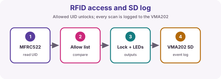
This is a logged access-control build. A card or fob presents a unique ID (UID). The sketch compares that UID with an allow list. Allowed cards unlock a driven lock coil briefly; denied cards flash red and beep. Every scan appends a line to ACCESS.LOG on the VMA202 SD card with a real calendar timestamp from the shield RTC.
It combines SPI (lesson 23), RTC/SD on the VMA202, millis output timing (lesson 28) and safe high-current drive (lesson 12).
RFID terms: PCD, PICC and UID
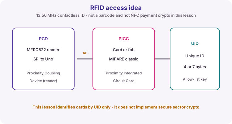
The MFRC522 board is a PCD (Proximity Coupling Device) - the reader. Cards and key fobs are PICCs (Proximity Integrated Circuit Cards). They talk over a 13.56 MHz RF field at short range.
Each tag carries a UID (Unique Identifier), usually 4 bytes and sometimes 7. This lesson uses the UID as a simple allow-list key. It does not implement MIFARE sector cryptography or payment-grade security - that is out of scope for this course.
| Term | Meaning |
|---|---|
| PCD | Reader module (MFRC522) |
| PICC | Card or fob presented to the reader |
| UID | Factory ID bytes used as the allow-list key |
| 13.56 MHz | HF RFID band used by common kit modules |
| Range | A few centimetres - hold the card near the antenna |
Typical kit reader, card and fob
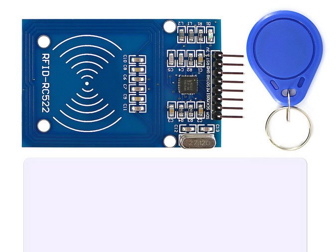
Most Arduino RFID kits include an MFRC522 (RC522) reader board, a white ISO-style card and a key fob. The large copper coil area on the module is the antenna - hold tags a few centimetres from that face. Pin labels on the header usually read SDA, SCK, MOSI, MISO, IRQ, GND, RST and 3.3V.
The card and fob are both PICCs at 13.56 MHz. Each has its own UID - enrol both if you want two allowed tokens, or enrol one and use the other as a deny test. Metal desks and stacking tags can weaken the read.
MFRC522 module pins
Kit modules usually label pins SDA, SCK, MOSI, MISO, IRQ, GND, RST and 3.3V. On this module SDA means SPI slave select (SS), not I2C data.
Power the reader from 3.3 V. Many MFRC522 boards are not 5 V tolerant on VCC. IRQ is unused in the worked sketch. Constructor: MFRC522 rfid(ssPin, rstPin).
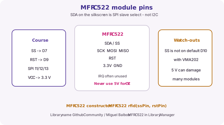
| Module label | Role | Course Uno pin |
|---|---|---|
| SDA / SS | SPI chip select | D7 |
| SCK | SPI clock | D13 |
| MOSI | SPI data out from Uno | D11 |
| MISO | SPI data in to Uno | D12 |
| RST | Reader reset | D9 |
| 3.3V | Module supply | 3.3 V |
| GND | Ground | GND |
| IRQ | Optional interrupt | Leave open |
What the VMA202 adds
The Velleman VMA202 is an Arduino-compatible data-logging shield. It stacks on the Uno and provides an SD card slot (FAT16/FAT32), a DS1307 RTC with CR1220 backup cell, stackable headers, a reset button, a small prototyping area (about 102 pads), and an onboard 3.3 V regulator sized for SD cards that draw more current.
In this lesson the shield is the logging half: every scan becomes a timestamped ACCESS.LOG line.
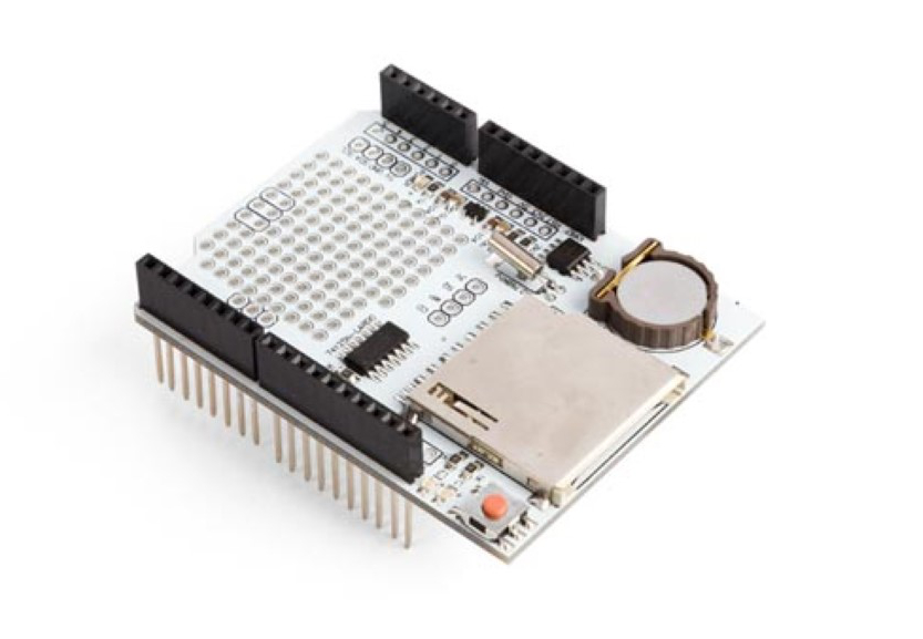
| Feature | Course use |
|---|---|
| SD card (SPI) | ACCESS.LOG file, CS on D10 |
| DS1307 RTC (I2C) | Date/time stamps on A4/A5 |
| CR1220 cell | Keeps RTC through Uno power loss |
| 3.3 V SD regulator | Supports SD cards that need more current |
| Proto pads | Optional soldering - not required for the worked build |
| Stackable headers | Shield sits on the Uno; wire RFID to free pins |
Shared SPI: two chip selects
The VMA202 SD card and the MFRC522 both use SPI. Share MOSI (D11), MISO (D12) and SCK (D13). Each device needs its own chip-select: VMA202 SD CS stays on D10; put MFRC522 SS on D7 and RST on D9.
Many generic RFID demos wire reader SS to D10. That conflicts with this shield. If the VMA202 is fitted, never put RFID SS on D10. Only one SPI slave should have its CS/SS line low at a time - the libraries manage that when you call their functions.
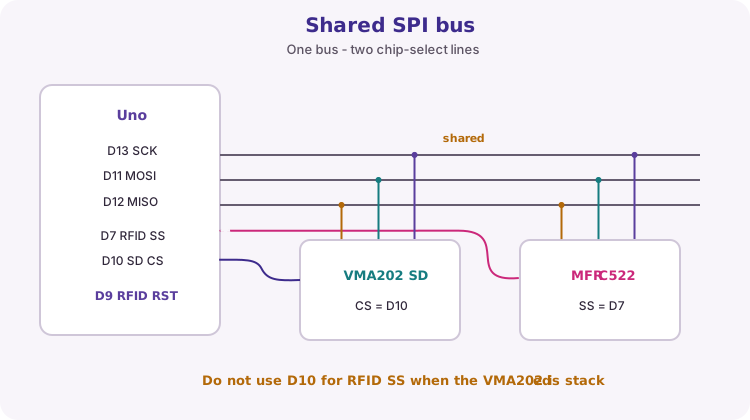
SPI.begin();
rfid.PCD_Init();          // talks on SS = D7
SD.begin(10);             // talks on CS = D10
// Never set both SS and CS low yourself at the same time
Course pin map
The breadboard photo under Wiring shows a complete RFID access idea (reader, LEDs, buzzer, FET load). Some demo diagrams (for example older Lesson 50 layouts) use different pin numbers, including RFID SS on D10. For this course with the VMA202 stacked, the table below is authoritative.
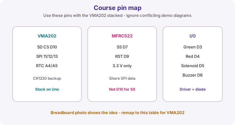
| Function | Uno pin |
|---|---|
| VMA202 SD CS | D10 |
| SPI MOSI / MISO / SCK | D11 / D12 / D13 |
| VMA202 RTC SDA / SCL | A4 / A5 |
| MFRC522 SS (SDA) | D7 |
| MFRC522 RST | D9 |
| MFRC522 VCC | 3.3 V (not 5 V) |
| Green LED | D3 |
| Red LED | D4 |
| Solenoid driver | D5 |
| Buzzer | D6 |
Integrate in order
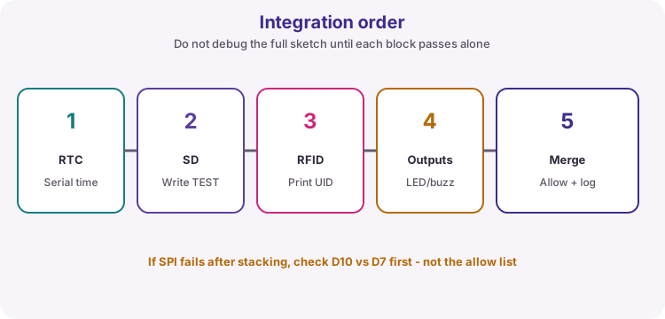
Do not start with the full sketch. Prove each subsystem, then merge:
1. VMA202 RTC prints time on Serial (lesson 19 set-once pattern). 2. SD.begin(10) succeeds; write and close a short test file. 3. RFID prints UIDs on Serial with SS on D7. 4. LEDs, buzzer and (safe) driver respond to forced allow/deny calls. 5. Merge allow-list logic and ACCESS.LOG writes.
If SPI fails only after stacking the shield, check D10 versus D7 first - not the allow list.
MFRC522 library call sequence
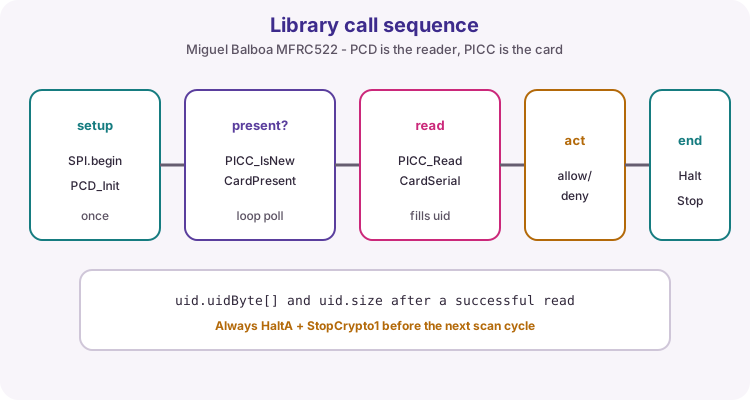
Install MFRC522 by GithubCommunity (Miguel Balboa) from Library Manager. In setup call SPI.begin() then rfid.PCD_Init(). Optional: rfid.PCD_DumpVersionToSerial() to confirm the chip answers.
In loop: if PICC_IsNewCardPresent() and PICC_ReadCardSerial() both succeed, uid.uidByte[] and uid.size hold the ID. After you finish acting and logging, call PICC_HaltA() and PCD_StopCrypto1() so the next scan can start cleanly.
if (!rfid.PICC_IsNewCardPresent()) return;
if (!rfid.PICC_ReadCardSerial()) return;
// use rfid.uid.uidByte and rfid.uid.size
rfid.PICC_HaltA();
rfid.PCD_StopCrypto1();
Enrol UIDs from Serial
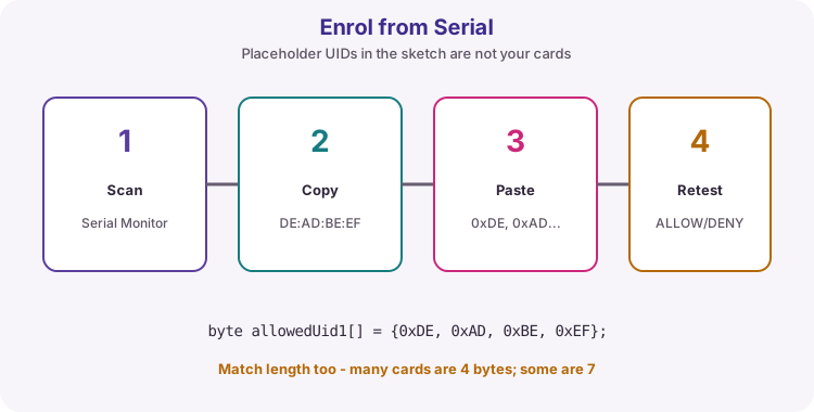
The sketch ships with placeholder UIDs. They are not your cards. Open Serial Monitor at 9600 baud, scan each tag, and copy the printed hex into allowedUid arrays as 0xNN bytes. Re-upload, then test one allowed and one denied card.
Match length as well as bytes: many kit cards are 4 bytes; some are 7. A 4-byte allow entry will never match a 7-byte UID.
// Serial printed: UID DE:AD:BE:EF
byte allowedUid1[] = {0xDE, 0xAD, 0xBE, 0xEF};
Allow and deny behaviour
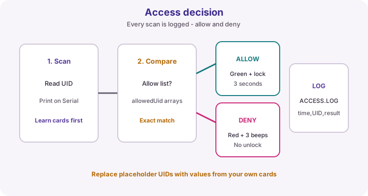
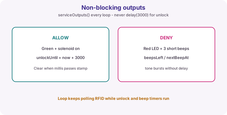
Allowed cards: green LED on, solenoid driver high for about three seconds, buzzer silent. Denied cards: red LED on, three short beeps, solenoid stays off. Both results are logged.
Outputs are timed with millis in serviceOutputs() so loop can keep running. Do not use delay(3000) for the unlock window - that would freeze RFID polling and beep timing.
| Result | Indicators | Lock |
|---|---|---|
| ALLOW | Green LED ~3 s | Driver high for unlock window |
| DENY | Red LED + 3 beeps | Driver stays low |
| Either | ACCESS.LOG line | Timestamp + UID + result |
Prepare the SD card and ACCESS.LOG
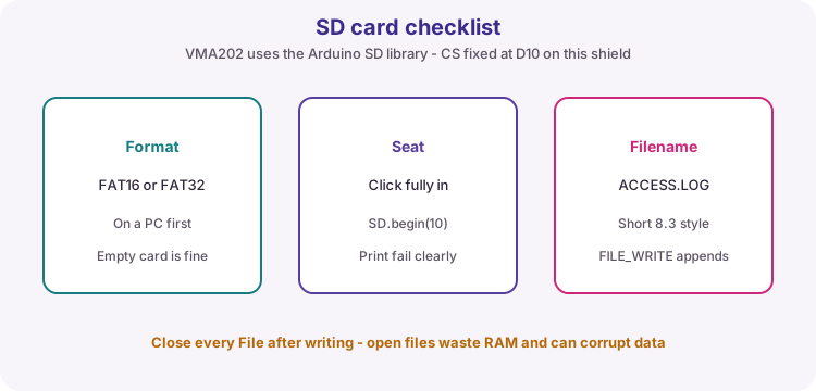
Format the microSD card FAT16 or FAT32 on a PC before first use. Seat it fully in the VMA202 slot. Call SD.begin(10) - CS is D10 on this shield.
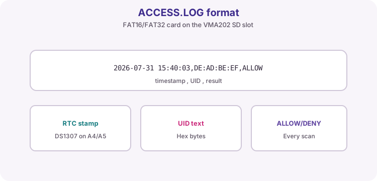
Use a short filename such as ACCESS.LOG (8.3 style is safest with the classic SD library). FILE_WRITE appends. Always close the File after each line. Each line is: timestamp, UID text, ALLOW or DENY.
Set the VMA202 RTC once (lesson 19). Adjust from compile time only when isrunning() is false (or lostPower() on a DS3231).
ACCESS.LOG line format
Example line: 2026-07-31 15:40:03,DE:AD:BE:EF,ALLOW
Pull the card and open the file on a PC in a text editor to prove logging for assessment. If the file is missing, SD.begin failed or the open/write path never ran.
Solenoid safety
Drive the lock coil with a MOSFET or transistor and a flyback diode from an external supply sized for the lock. Join grounds with the Uno. Never power a solenoid from an Uno pin.
The breadboard photo shows an N-FET low-side switch with a diode across the inductive load - same idea as lesson 12. If you have no lock yet, treat D5 as a logic indicator LED through a resistor while you prove the software path.
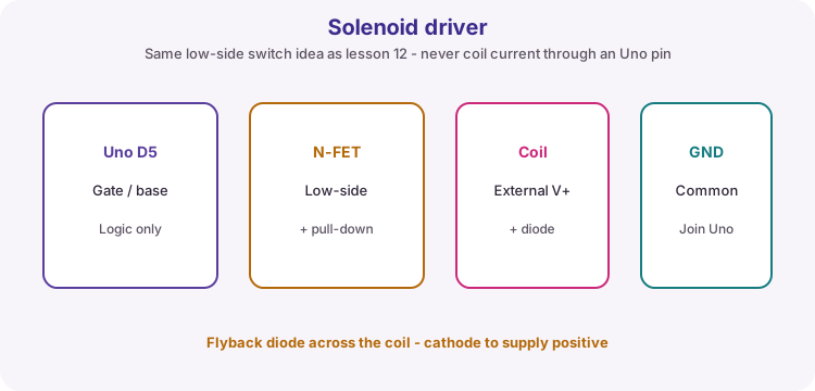
| Rule | Why |
|---|---|
| External coil supply | Solenoid current is far above Uno pin limits |
| Common GND | Driver and Uno must share a return path |
| Flyback diode | Stops inductive spikes damaging the FET |
| Gate resistor / pull-down | Clean off state when the pin floats at reset |
Assessment evidence
A complete demo pack for this module usually includes:
1. Pin map showing D10 reserved for SD and D7 for RFID SS 2. Serial capture of enrolment UIDs 3. Commented sketch with named pins and allow-list bytes 4. ACCESS.LOG excerpt with ALLOW and DENY lines 5. Photo or note of the FET/diode lock drive (or LED stand-in) 6. One fault found (often SPI CS clash or 5 V on the reader) and how you fixed it
Wiring and safe build sequence
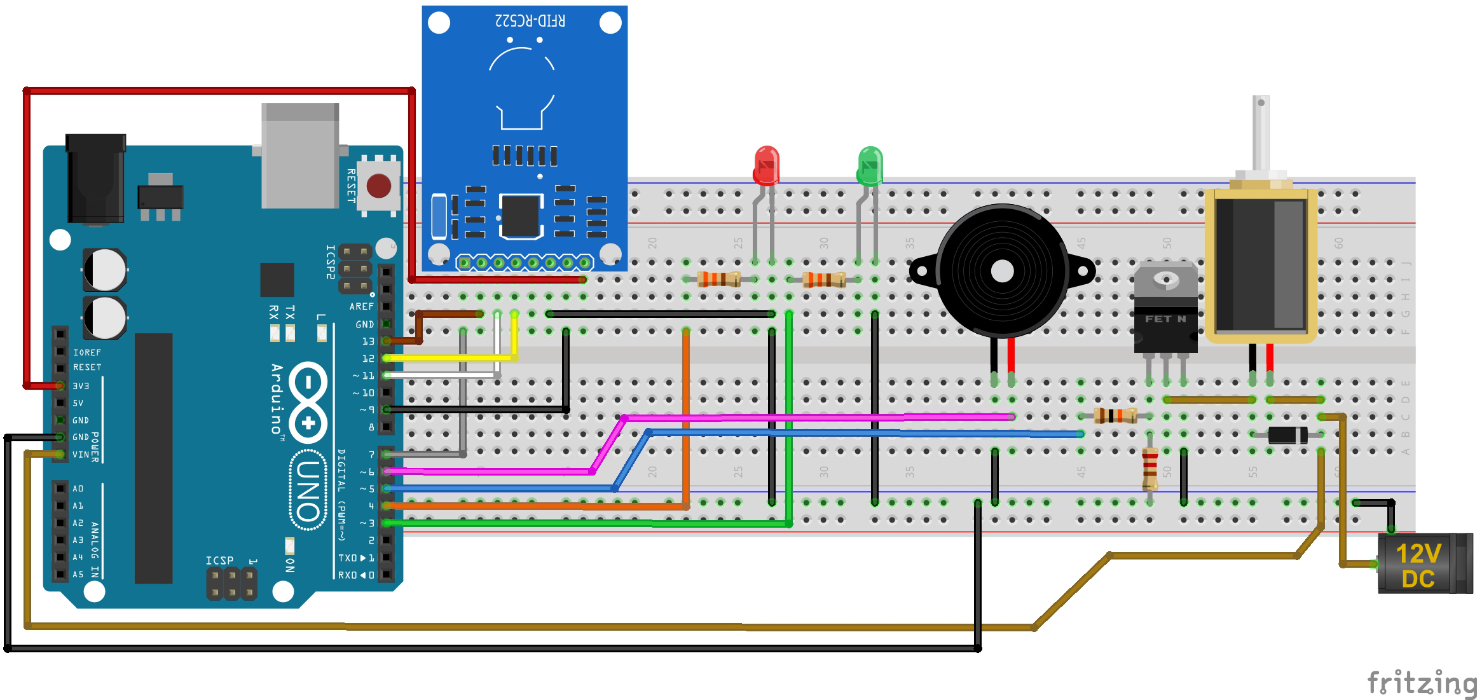
- Stack VMA202 on the Uno (SD CS D10, MOSI D11, MISO D12, SCK D13, RTC A4/A5); fit CR1220; insert FAT16/FAT32 microSD
- MFRC522 SDA/SS -> D7 (not D10)
- MFRC522 RST -> D9
- MFRC522 MOSI -> D11, MISO -> D12, SCK -> D13
- MFRC522 3.3 V -> 3.3 V, GND -> GND (do not use 5 V for VCC on typical modules)
- Green LED: D3 -> 330 ohm -> LED anode; cathode -> GND
- Red LED: D4 -> 330 ohm -> LED anode; cathode -> GND
- Passive buzzer signal -> D6; other side -> GND
- Solenoid driver gate/base -> D5; coil on external supply with flyback diode; commons joined to Uno GND
Worked sketch
Download .ino sketch#include <SPI.h>
#include <MFRC522.h>
#include <SD.h>
#include <Wire.h>
#include <RTClib.h>
const byte sdCsPin = 10; // VMA202 SD chip select
const byte rfidSsPin = 7; // MFRC522 SDA/SS (not D10)
const byte rfidRstPin = 9;
const byte greenLed = 3;
const byte redLed = 4;
const byte solenoidPin = 5;
const byte buzzerPin = 6;
MFRC522 rfid(rfidSsPin, rfidRstPin);
RTC_DS1307 rtc;
// RTC_DS3231 rtc; // use this instead if your module is a DS3231
// Replace these UIDs with cards scanned from Serial during setup/testing.
byte allowedUid1[] = {0xDE, 0xAD, 0xBE, 0xEF};
byte allowedUid2[] = {0x01, 0x23, 0x45, 0x67};
unsigned long unlockUntil = 0;
unsigned long denyUntil = 0;
unsigned long nextBeepAt = 0;
byte beepsLeft = 0;
bool uidMatches(byte *uid, byte *allowed, byte length) {
for (byte i = 0; i < length; i++) {
if (uid[i] != allowed[i]) return false;
}
return true;
}
bool isAllowed(byte *uid, byte length) {
if (length == sizeof(allowedUid1) && uidMatches(uid, allowedUid1, length)) return true;
if (length == sizeof(allowedUid2) && uidMatches(uid, allowedUid2, length)) return true;
return false;
}
void uidToText(byte *uid, byte length, char *out, byte outSize) {
byte pos = 0;
out[0] = 0;
for (byte i = 0; i < length; i++) {
if ((pos + 3) >= outSize) break;
sprintf(&out[pos], "%02X", uid[i]);
pos += 2;
if (i + 1 < length && (pos + 1) < outSize) {
out[pos++] = ':';
out[pos] = 0;
}
}
}
void logEvent(const char *uidText, bool allowed) {
DateTime now = rtc.now();
File logFile = SD.open("ACCESS.LOG", FILE_WRITE);
if (!logFile) {
Serial.println("SD log open failed");
return;
}
char stamp[20];
snprintf(stamp, sizeof(stamp), "%04d-%02d-%02d %02d:%02d:%02d",
now.year(), now.month(), now.day(),
now.hour(), now.minute(), now.second());
logFile.print(stamp);
logFile.print(",");
logFile.print(uidText);
logFile.print(",");
logFile.println(allowed ? "ALLOW" : "DENY");
logFile.close();
}
void startAllow() {
digitalWrite(redLed, LOW);
digitalWrite(greenLed, HIGH);
digitalWrite(solenoidPin, HIGH);
noTone(buzzerPin);
unlockUntil = millis() + 3000;
denyUntil = 0;
beepsLeft = 0;
Serial.println("ALLOW");
}
void startDeny() {
digitalWrite(greenLed, LOW);
digitalWrite(solenoidPin, LOW);
digitalWrite(redLed, HIGH);
denyUntil = millis() + 900;
beepsLeft = 3;
nextBeepAt = millis();
unlockUntil = 0;
Serial.println("DENY");
}
void serviceOutputs() {
unsigned long now = millis();
if (unlockUntil != 0 && now >= unlockUntil) {
digitalWrite(solenoidPin, LOW);
digitalWrite(greenLed, LOW);
unlockUntil = 0;
}
if (beepsLeft > 0 && now >= nextBeepAt) {
tone(buzzerPin, 1800, 80);
beepsLeft--;
nextBeepAt = now + 180;
}
if (denyUntil != 0 && now >= denyUntil) {
digitalWrite(redLed, LOW);
noTone(buzzerPin);
denyUntil = 0;
}
}
void setup() {
pinMode(greenLed, OUTPUT);
pinMode(redLed, OUTPUT);
pinMode(solenoidPin, OUTPUT);
pinMode(buzzerPin, OUTPUT);
digitalWrite(solenoidPin, LOW);
Serial.begin(9600);
while (!Serial && millis() < 2000) {
/* wait briefly for USB Serial on some boards */
}
SPI.begin();
rfid.PCD_Init();
Serial.print("MFRC522 version: 0x");
Serial.println(rfid.PCD_ReadRegister(rfid.VersionReg), HEX);
Wire.begin();
if (!rtc.begin()) {
Serial.println("RTC missing on VMA202");
}
// Set compile time ONLY if the clock stopped (DS3231: use rtc.lostPower())
if (!rtc.isrunning()) {
rtc.adjust(DateTime(F(__DATE__), F(__TIME__)));
}
if (!SD.begin(sdCsPin)) {
Serial.println("VMA202 SD init failed (CS=D10)");
} else {
Serial.println("VMA202 SD ready");
}
Serial.println("Scan a card to learn its UID, then update allowedUid arrays.");
}
void loop() {
serviceOutputs();
if (!rfid.PICC_IsNewCardPresent() || !rfid.PICC_ReadCardSerial()) {
return;
}
char uidText[24];
uidToText(rfid.uid.uidByte, rfid.uid.size, uidText, sizeof(uidText));
Serial.print("UID ");
Serial.print(uidText);
Serial.print(" (");
Serial.print(rfid.uid.size);
Serial.println(" bytes)");
bool allowed = isAllowed(rfid.uid.uidByte, rfid.uid.size);
logEvent(uidText, allowed);
if (allowed) startAllow();
else startDeny();
rfid.PICC_HaltA();
rfid.PCD_StopCrypto1();
}How the code works
- VMA202 SD chip select is D10; RFID SS must be a different pin (D7 here).
- Replace allowedUid1/allowedUid2 with UIDs printed on Serial; match byte length as well as values.
- isAllowed uses sizeof(allowedUid) so 4-byte and 7-byte entries can coexist if you add them carefully.
- Allow holds green LED + solenoid for 3 s using millis. Deny keeps red LED on while three short beeps play.
- RTC adjusts from compile time only when isrunning() is false (lesson 19 pattern).
- VersionReg print is a quick sanity check that the MFRC522 answered on SPI after PCD_Init.
Test and record evidence
Practical evidence checklist
Common faults and checks
- SD fails: format FAT16/FAT32, confirm CS=10, seat the card fully, close files after writes.
- RFID silent / version 0x00 or 0xFF: check 3.3 V to the reader, SPI wires, and SS on D7 not D10.
- Everything denied: copy the Serial UID into allowedUid1 exactly; check 4 vs 7 byte length.
- Repeated ghost scans: ensure HaltA and StopCrypto1 run after each successful read.
- Solenoid weak/resets board: use an external coil supply and common GND.
- Breadboard photo pins differ: remap to the course table when the VMA202 is stacked.
- Wrong timestamps: fit/replace CR1220 and set RTC once when isrunning() is false.
Check your understanding
Q1. What do PCD and PICC mean in this lesson?
Show answer
PCD is the reader (MFRC522); PICC is the card or fob.
Q2. Which VMA202 pin is SD chip select?
Show answer
D10.
Q3. Why must MFRC522 SS avoid D10 when the VMA202 is stacked?
Show answer
D10 is already used by the VMA202 SD card CS on the shared SPI bus.
Q4. What voltage should power a typical MFRC522 module VCC?
Show answer
3.3 V.
Q5. On the MFRC522 module, what does the SDA label usually mean?
Show answer
SPI slave select (SS), not I2C data.
Q6. What three fields go in each ACCESS.LOG line?
Show answer
Timestamp, UID text, and ALLOW or DENY.
Q7. Why call PICC_HaltA and PCD_StopCrypto1 after a read?
Show answer
To finish the card session cleanly so the next scan can be detected.
Q8. Why use millis for the 3 s unlock instead of delay(3000)?
Show answer
delay would freeze loop, blocking RFID polling and beep timing.