
24. 4x4 Matrix Keypad
Read a membrane keypad with the Keypad library and print each press on Serial.
Learning outcomes
- Explain how a 4x4 pad uses eight wires for sixteen keys
- Wire ribbon pins 1-8 to D9-D2 without using D0/D1
- Install and use the Keypad library (Mark Stanley / Alexander Brevig)
- Match the keys[] map to the printed labels on your pad
- Use getKey() non-blocking to print or build a PIN entry
Parts and preparation
Arduino Uno (on-board LED on pin 13), USB data cable, 4x4 membrane keypad (8-pin ribbon), jumper wires, and Keypad by Mark Stanley / Alexander Brevig (Library Manager).
Before power: inspect wiring, confirm supply voltage and ensure all connected circuits share GND.
Libraries for this lesson
In Arduino IDE 2 open Tools → Manage Libraries…. Search by the Library Manager name and install the package by the exact author below. Similar names from other authors can use different APIs and will break the example.
| Include | Library Manager name | Author | Install note |
|---|---|---|---|
Keypad.h | Keypad | Mark Stanley, Alexander Brevig | Library Manager: search Keypad and install Keypad by Mark Stanley, Alexander Brevig. |
Matrix scanning
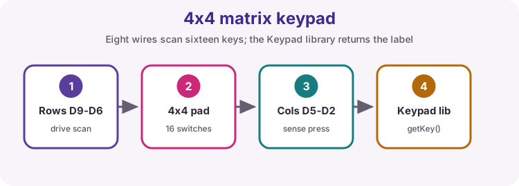
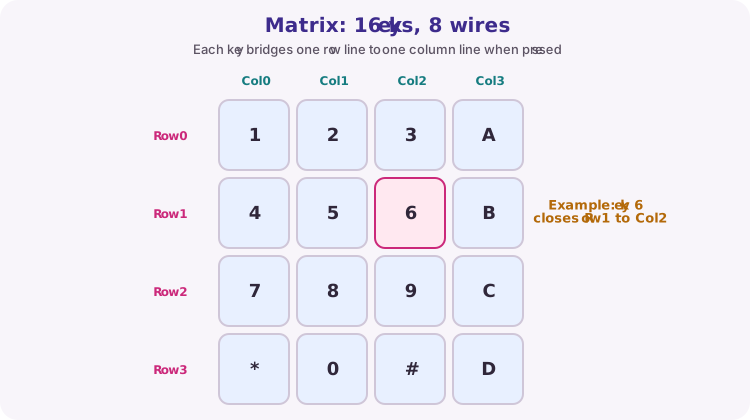
A 4x4 pad has 16 switches but only eight wires: four rows and four columns. Each key sits at one row-column crossing. Pressing a key connects that row wire to that column wire.
The Keypad library drives the row pins and reads the column pins (with internal pull-ups) so you get one character when a key closes that intersection. You do not need a separate VCC or GND on a typical membrane pad - only the eight matrix lines.
Ribbon pin order
Count keypad pins from left to right on the ribbon as seen from the button side: pins 1-4 are rows, pins 5-8 are columns. This lesson uses rowPins D9-D6 and colPins D5-D2.
Leave D0 and D1 free - USB Serial uses them on the Uno. The breadboard photo under Wiring shows the physical course build.
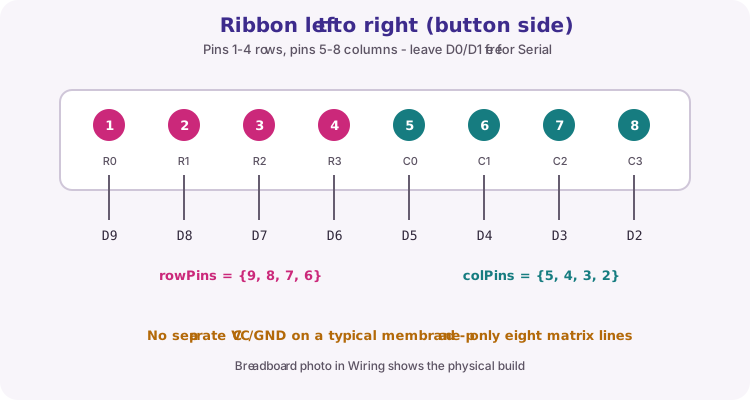
| Keypad pin (L to R) | Role | Uno pin |
|---|---|---|
| 1 | Row 0 | D9 |
| 2 | Row 1 | D8 |
| 3 | Row 2 | D7 |
| 4 | Row 3 | D6 |
| 5 | Col 0 | D5 |
| 6 | Col 1 | D4 |
| 7 | Col 2 | D3 |
| 8 | Col 3 | D2 |
keys[] must match the pad
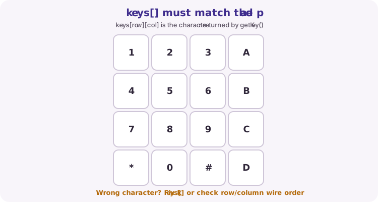
The keys[] array is the printed label grid: keys[row][col] is what getKey() returns for that crossing. If a press prints the wrong character, fix the map or check that row/column wires are not reversed.
makeKeymap(keys) links that grid to the scanned matrix when you construct the Keypad object.
char keys[ROWS][COLS] = {
  {'1', '2', '3', 'A'},
  {'4', '5', '6', 'B'},
  {'7', '8', '9', 'C'},
  {'*', '0', '#', 'D'}
};
getKey() behaviour
getKey() is non-blocking: it returns the pressed character once per new press, or 0 / NO_KEY when idle. Use if (pressedKey) so you only print or act when a new key is detected.
Example 2 builds a short PIN string from digits and treats # as Enter. That is the same getKey() pattern with a little state.
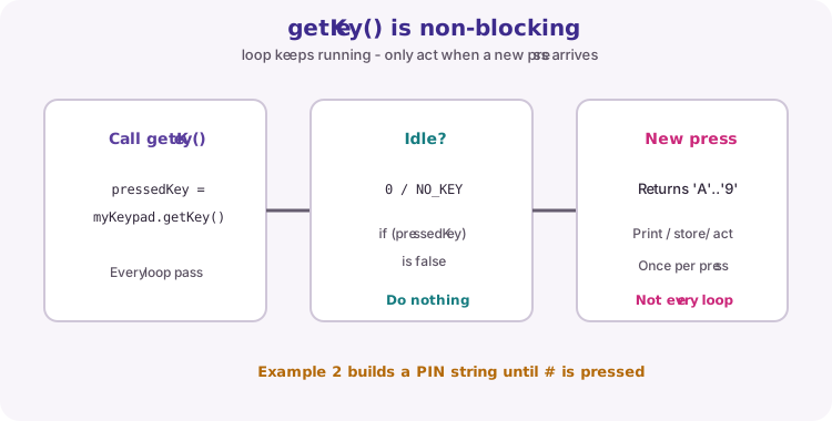
char pressedKey = myKeypad.getKey();
if (pressedKey) {
  Serial.println(pressedKey);
}
Wiring and safe build sequence
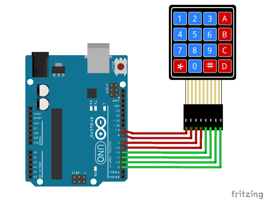
- Keypad pin 1 (leftmost) -> D9
- Keypad pin 2 -> D8
- Keypad pin 3 -> D7
- Keypad pin 4 -> D6
- Keypad pin 5 -> D5
- Keypad pin 6 -> D4
- Keypad pin 7 -> D3
- Keypad pin 8 (rightmost) -> D2
- No separate VCC/GND on a typical membrane pad - only the eight matrix lines
Worked sketch
Download .ino sketch#include <Keypad.h>
const byte ROWS = 4;
const byte COLS = 4;
char keys[ROWS][COLS] = {
{'1', '2', '3', 'A'},
{'4', '5', '6', 'B'},
{'7', '8', '9', 'C'},
{'*', '0', '#', 'D'}
};
byte rowPins[ROWS] = {9, 8, 7, 6};
byte colPins[COLS] = {5, 4, 3, 2};
Keypad myKeypad = Keypad(makeKeymap(keys), rowPins, colPins, ROWS, COLS);
void setup() {
Serial.begin(9600);
Serial.println("Keypad ready. Press any key...");
}
void loop() {
char pressedKey = myKeypad.getKey();
if (pressedKey) {
Serial.print("Key pressed: ");
Serial.println(pressedKey);
}
}How the code works
- Install Keypad by Mark Stanley / Alexander Brevig before Verify.
- makeKeymap(keys) links your label grid to the scanned matrix.
- getKey() returns 0 when no new press is available; if (pressedKey) is enough for beginners.
- Match Serial Monitor baud to 9600.
Example 2: PIN lock on LED 13
Download .ino sketchWhat this sketch is for: Same keypad wiring. Uses the built-in LED on pin 13 (LED_BUILTIN). Type up to four digits (Serial shows * for each), then press # to check. Correct code 1234# turns the LED on for 3 seconds. Any other entry ending with # flashes the LED three times at 100 ms on / 100 ms off.
#include <Keypad.h>

// ---- Keypad setup ----
const byte ROWS = 4;  // 4 rows on the keypad
const byte COLS = 4;  // 4 columns on the keypad

// What each button on the keypad represents
char keys[ROWS][COLS] = {
  {'1', '2', '3', 'A'},
  {'4', '5', '6', 'B'},
  {'7', '8', '9', 'C'},
  {'*', '0', '#', 'D'}
};

// Which Arduino pins are connected to the keypad's rows and columns
byte rowPins[ROWS] = {9, 8, 7, 6};
byte colPins[COLS] = {5, 4, 3, 2};

Keypad myKeypad = Keypad(makeKeymap(keys), rowPins, colPins, ROWS, COLS);

// ---- Code / password setup ----
const String secretCode = "1234";  // the correct code
String inputCode = "";             // what the user has typed so far

void setup() {
  pinMode(LED_BUILTIN, OUTPUT);
  digitalWrite(LED_BUILTIN, LOW);
  Serial.begin(9600);
  Serial.println("Enter code, then press #");
}

void loop() {
  char key = myKeypad.getKey();

  // If no button was pressed, do nothing this round
  if (key == NO_KEY) {
    return;
  }

  // '#' means "check the code now"
  if (key == '#') {
    Serial.println();  // move to a new line in Serial Monitor

    if (inputCode == secretCode) {
      Serial.println("Access Granted!");
      digitalWrite(LED_BUILTIN, HIGH);
      delay(3000);
      digitalWrite(LED_BUILTIN, LOW);
    } else {
      Serial.println("Access Denied!");
      flashErrorLED();
    }

    inputCode = "";  // reset for next attempt
  }
  // Only accept digits 0-9, and only if there's room left
  else if (key >= '0' && key <= '9' && inputCode.length() < 4) {
    inputCode += key;   // add the digit to the code
    Serial.print("*");  // print * to hide the code (use key instead to show it)
  }
}

// Blinks the LED quickly 3 times to show a wrong code
void flashErrorLED() {
  for (byte i = 0; i < 3; i++) {
    digitalWrite(LED_BUILTIN, HIGH);
    delay(100);
    digitalWrite(LED_BUILTIN, LOW);
    delay(100);
  }
}
How the code works
- Digits build inputCode; # is Enter and compares it to secretCode.
- Serial prints * for each digit so the PIN is not shown in the Monitor.
- Correct (1234#): LED on for 3000 ms. Wrong: flashErrorLED() does three 100 ms flashes.
- A B C D * are ignored. Change Serial.print("*") to Serial.print(key) if you want to see the digits while testing.
Test and record evidence
Practical evidence checklist
Common faults and checks
- Install failed or Keypad.h missing: use Library Manager and restart the IDE.
- Wrong character for a key: check the keys[] layout against the printed pad, and confirm row/column pin order.
- No response: reseat the ribbon, confirm D2-D9 wiring, and avoid using D0/D1 for the pad.
- Ghost or stuck keys: press one key at a time; check for bent ribbon pins or a short on the breadboard adapters.
- PIN lock: type digits then # to enter. Without # nothing is checked. Letters and * are ignored.
Check your understanding
Q1. Why does a 4x4 pad need only eight wires?
Show answer
Keys share four row and four column lines in a matrix.
Q2. What does getKey() return when no key was newly pressed?
Show answer
0 / NO_KEY (treated as false in if (pressedKey)).
Q3. Why avoid D0 and D1 for the keypad in this lesson?
Show answer
Those pins are used by USB Serial on the Uno.
Q4. What must keys[] match?
Show answer
The labels printed on your physical pad for each row/column position.