
27. Capstone 2: Clock, Alarm & Servo
Share I2C between RTC and LCD, then drive a servo and buzzer from alarm states without blocking delays.
Learning outcomes
- Share one I2C bus between an RTC and an I2C LCD using different addresses
- Compare RTC hour and minute to a documented alarm setting
- Implement NORMAL, ALARMING and ACKNOWLEDGED states with a button
- Drive a servo and buzzer safely with common GND
- Show fixed-width time and status text on a 16x2 LCD
Parts and preparation
Uno, DS1307 (or DS3231 / PCF8523) RTC module with backup cell, I2C 1602 LCD, passive buzzer, push-button, servo with a suitable 5 V supply and common GND. Install the same libraries as lessons 13, 17 and 19.
Before power: inspect wiring, confirm supply voltage and ensure all connected circuits share GND.
Libraries for this lesson
In Arduino IDE 2 open Tools → Manage Libraries…. Search by the Library Manager name and install the package by the exact author below. Similar names from other authors can use different APIs and will break the example.
| Include | Library Manager name | Author | Install note |
|---|---|---|---|
Wire.h | Wire | Arduino | Built into the Arduino core. No Library Manager install required. |
RTClib.h | RTClib | Adafruit | Same package as lesson 19. Install via Library Manager. |
Servo.h | Servo | Arduino | Built-in with Arduino AVR Boards. No Library Manager install required. |
LiquidCrystal_I2C.h | LiquidCrystal I2C | Frank de Brabander | Same package as lesson 17. Install via Library Manager. |
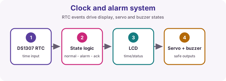
Capstone goal
This build combines RTC timekeeping (lesson 19), I2C LCD (lesson 17), a button, a buzzer and a servo (lesson 13). The RTC decides when the alarm window opens. The button acknowledges the event. The LCD shows clock and status; the servo and buzzer are the actuators.
Design the states on paper before you merge sketches.
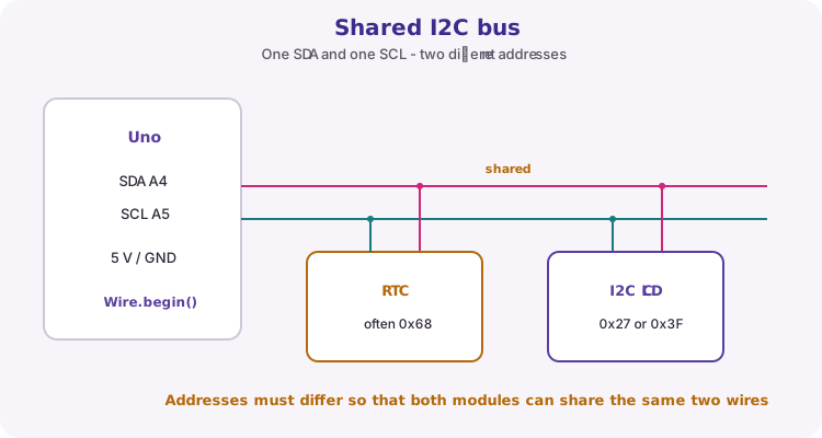
Shared I2C: RTC and LCD
Both modules share SDA (A4) and SCL (A5). That works because they use different I2C addresses: RTC chips are often 0x68; LCD backpacks are commonly 0x27 or 0x3F.
Course default object is RTC_DS1307. Kits and breadboard photos may show a DS3231 or PCF8523 - keep the wiring, swap the RTClib type, and use lostPower() where that chip requires it (lesson 19).
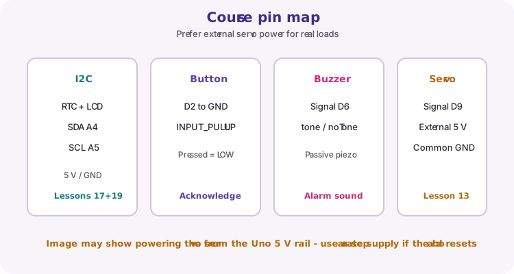
Course pin map
The breadboard photo under Wiring matches the course pin list: shared I2C, acknowledge button on D2, buzzer on D6, servo signal on D9.
| Function | Uno pin |
|---|---|
| RTC + LCD SDA / SCL | A4 / A5 |
| Acknowledge button | D2 to GND, INPUT_PULLUP |
| Passive buzzer | D6 |
| Servo signal | D9 |
| Servo power | External 5 V preferred; common GND |
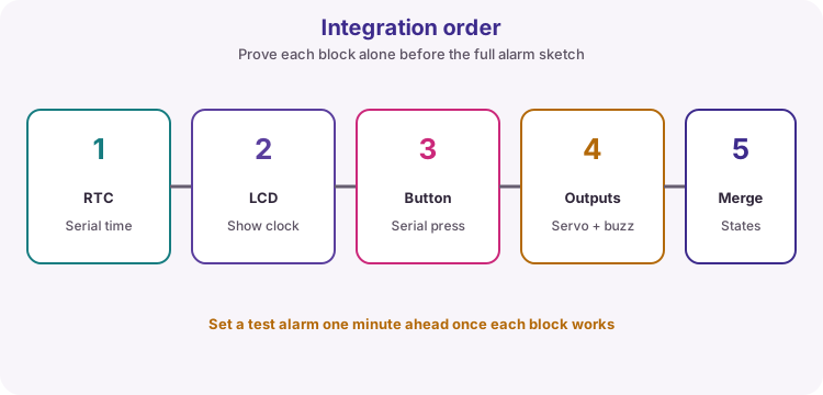
Integrate in order
Prove RTC time on Serial, then LCD clock text, then button presses, then servo and buzzer moves, then merge the alarm state logic.
For a quick demo, set alarmHour and alarmMinute one minute ahead of the RTC reading.
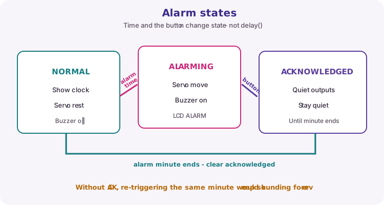
Alarm states
Three behaviours keep the demo clear:
NORMAL - clock display, servo at rest, buzzer off. ALARMING - alarm hour and minute match, and the event is not yet acknowledged: move servo and sound buzzer. ACKNOWLEDGED - button pressed during the alarm minute: silence outputs and stay quiet until that minute ends.
When the RTC leaves the alarm minute, clear acknowledged so the next day (or next test) can fire again.
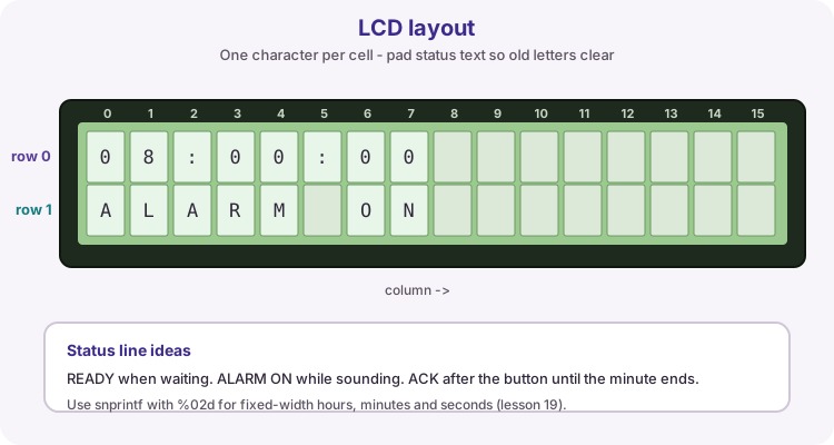
LCD time and status
Row 0 shows HH:MM:SS with snprintf and %02d so single-digit hours do not shift the layout (lesson 19). Row 1 shows READY, ALARM ON or ACK - pad with spaces so old letters do not linger.
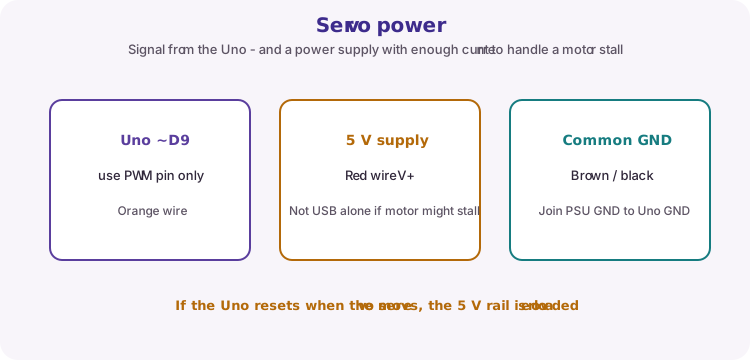
Servo power safety
The Uno drives only the servo signal on D9. Stall current often exceeds what USB or the onboard regulator can feed. Prefer an external 5 V supply for the red wire and join grounds with the Uno.
The breadboard photo may show the servo on the Uno 5 V rail for a light demo. If the board resets when the arm moves, move motor power off the Uno immediately.
| Rule | Why |
|---|---|
| External servo V+ | Avoids brown-out resets under load |
| Common GND | Signal needs a shared return path |
| Soft end angles | Rest and alarm angles must not bind the mechanism |
| Backup cell in RTC | Time must survive Uno power loss for a fair demo |
Assessment evidence
Prepare the same style of pack as Capstone 1:
1. Block / state diagram 2. Wiring diagram or annotated breadboard photo 3. Commented sketch with named pins and alarm constants 4. Test table: before alarm, during alarm, after acknowledge, after minute ends 5. Power-cycle check that RTC time is retained 6. One fault found and fixed
Wiring and safe build sequence
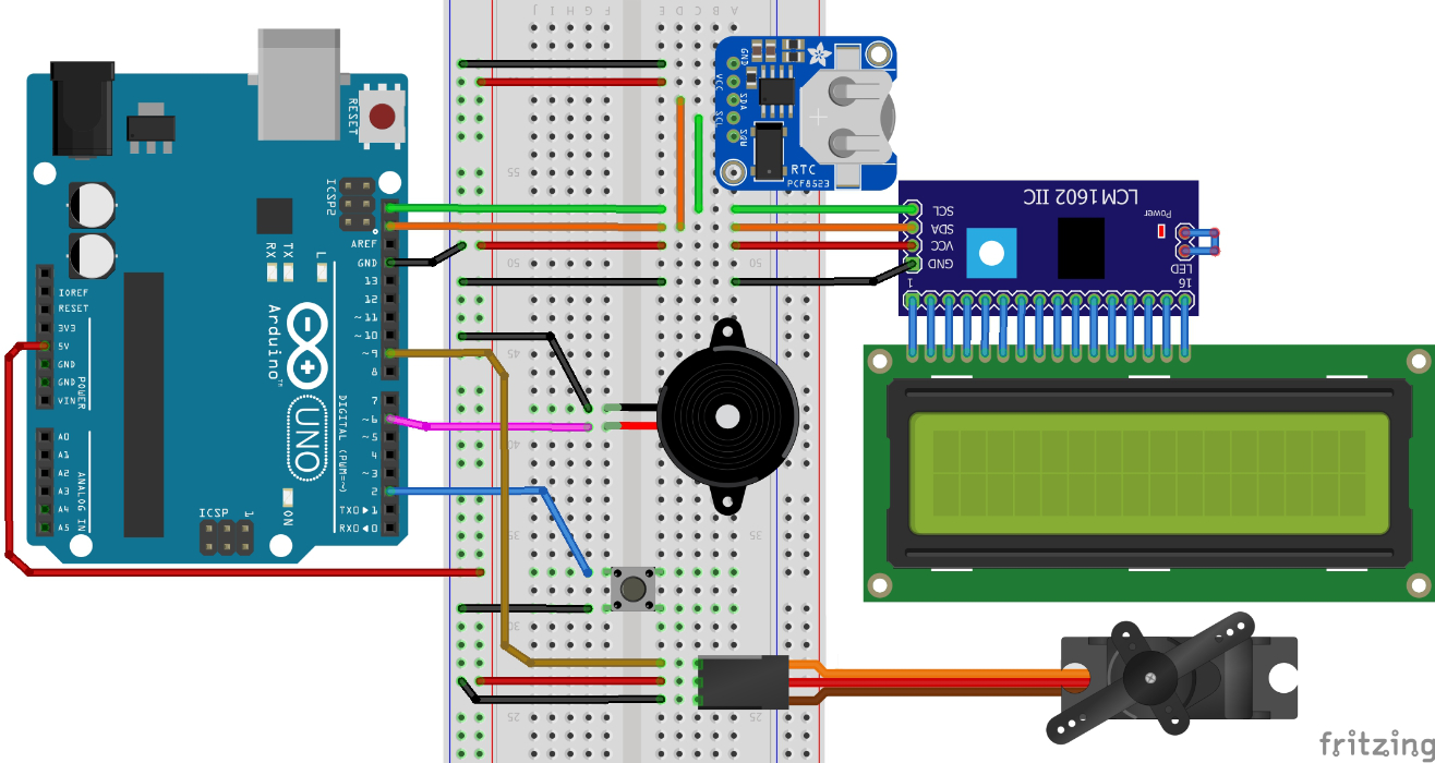
- 5 V and GND to breadboard rails; all modules share GND
- RTC VCC/GND -> 5 V/GND; SDA -> A4; SCL -> A5; fit backup cell
- I2C LCD VCC/GND -> 5 V/GND; SDA -> A4; SCL -> A5 (same bus as RTC)
- Acknowledge button: one side -> D2, other side -> GND (INPUT_PULLUP in code)
- Passive buzzer signal -> D6; other side -> GND
- Servo signal (orange/yellow) -> D9; V+ from external 5 V preferred; GND -> common GND
Worked sketch
Download .ino sketch#include <Wire.h>
#include <RTClib.h>
#include <LiquidCrystal_I2C.h>
#include <Servo.h>
const byte buttonPin = 2;
const byte buzzerPin = 6;
const byte servoPin = 9;
const byte alarmHour = 8; // Change for a one-minute-ahead bench test
const byte alarmMinute = 0;
const int servoRest = 10;
const int servoAlarm = 90;
RTC_DS1307 rtc;
// RTC_DS3231 rtc; // use instead if your module is a DS3231
// RTC_PCF8523 rtc; // use instead if your module is a PCF8523
LiquidCrystal_I2C lcd(0x27, 16, 2); // Try 0x3F if the display stays blank
Servo latch;
bool acknowledged = false;
void showStatus(const char *status) {
lcd.setCursor(0, 1);
lcd.print(status);
lcd.print(" "); // pad / clear to end of row
}
void setup() {
pinMode(buttonPin, INPUT_PULLUP);
pinMode(buzzerPin, OUTPUT);
noTone(buzzerPin);
Serial.begin(9600);
Wire.begin();
lcd.init();
lcd.backlight();
latch.attach(servoPin);
latch.write(servoRest);
if (!rtc.begin()) {
lcd.print("RTC missing");
Serial.println("RTC missing");
while (true) { /* halt */ }
}
// Set compile time ONLY if the clock stopped (DS3231: use rtc.lostPower())
if (!rtc.isrunning()) {
rtc.adjust(DateTime(F(__DATE__), F(__TIME__)));
}
lcd.clear();
showStatus("READY");
Serial.println("Clock alarm ready");
}
void loop() {
DateTime now = rtc.now();
bool alarmTime = (now.hour() == alarmHour) && (now.minute() == alarmMinute);
if (digitalRead(buttonPin) == LOW) {
acknowledged = true;
}
if (!alarmTime) {
acknowledged = false;
}
char line0[17];
snprintf(line0, sizeof(line0), "%02d:%02d:%02d",
now.hour(), now.minute(), now.second());
lcd.setCursor(0, 0);
lcd.print(line0);
lcd.print(" ");
if (alarmTime && !acknowledged) {
latch.write(servoAlarm);
tone(buzzerPin, 1200);
showStatus("ALARM ON");
} else if (alarmTime && acknowledged) {
latch.write(servoRest);
noTone(buzzerPin);
showStatus("ACK");
} else {
latch.write(servoRest);
noTone(buzzerPin);
showStatus("READY");
}
}How the code works
- alarmHour / alarmMinute are the documented trigger - set them one minute ahead for a bench demo.
- Acknowledged clears when the RTC leaves the alarm minute so the next event can fire.
- Swap RTC_DS1307 for RTC_DS3231 or RTC_PCF8523 if that matches your module (lesson 19).
- Prefer external servo 5 V with common GND if USB power browns out during movement.
Test and record evidence
Practical evidence checklist
Common faults and checks
- RTC missing / wrong time: check A4/A5, backup cell, and set-once with isrunning()/lostPower().
- Blank LCD: I2C scanner; try address 0x3F; confirm shared SDA/SCL with the RTC.
- Alarm never fires: print hour/minute on Serial and set alarmHour/alarmMinute one minute ahead.
- Button does nothing: D2 to GND, INPUT_PULLUP, pressed reads LOW.
- Uno resets when servo moves: move servo V+ to an external 5 V supply and join GND.
Check your understanding
Q1. Why can RTC and LCD share I2C wires?
Show answer
They have different bus addresses.
Q2. What is the purpose of an acknowledged state?
Show answer
It records that the user silenced the current alarm event for the rest of that minute.
Q3. Why prefer external power for the servo?
Show answer
Stall current can brown out the Uno if the servo draws from the board 5 V rail.
Q4. When should acknowledged be cleared?
Show answer
When the RTC is no longer in the alarm hour and minute.