
34. Introducing the ESP32 Family
Meet the ESP32 family, learn classic DevKit anatomy, install Espressif support, and complete a reliable first blink/Serial upload.
Learning outcomes
- Explain how ESP32-class boards differ from Arduino Uno R3
- Identify EN, BOOT, USB, 3V3/GND/5V and GPIO headers on a classic DevKit
- Compare classic ESP32, ESP32-C3, ESP32-C5, ESP32-C6 and ESP32-P4 at a high level
- Add the Espressif ESP32 board package and select ESP32 Dev Module for course labs
- Upload a first sketch, open Serial at 115200, and fix common port/BOOT faults
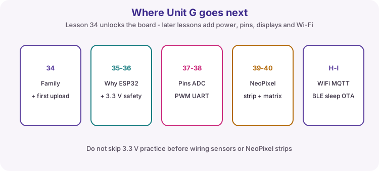
- Apply 3.3 V I/O safety and know what Units G-I cover next
Parts and preparation
Arduino IDE 2, USB data cable (not charge-only), and one ESP32-family board. Course practicals default to a classic ESP32 DevKit (ESP32 Dev Module). C3/C5/C6/P4 are fine for this intro if you pick the matching Board menu entry.
Before power: inspect wiring, confirm supply voltage and ensure all connected circuits share GND.
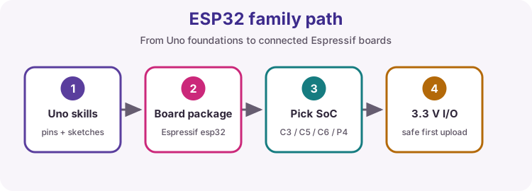
What is the ESP32 family?
ESP32 is a family of microcontrollers from Espressif. Most members are used for Wi-Fi and Bluetooth projects; ESP32-P4 is the high-performance HMI / edge-compute branch and does not include on-chip Wi-Fi or Bluetooth. You still program them from Arduino IDE 2, but with the Espressif board package instead of the Uno AVR core.
Units A-F stay the foundation for pins, sketches and safe wiring. Units G-I extend that skill set for 3.3 V practice, NeoPixel displays, Wi-Fi, MQTT, BLE, sleep and OTA.
Course default board
Unless a lesson says otherwise, Unit G-I practicals assume a classic ESP32 DevKit and the IDE entry Tools -> Board -> esp32 -> ESP32 Dev Module.
C3, C5, C6 and P4 boards are part of the family overview so you can recognise them in shops and datasheets. Their GPIO maps and Board menu names differ - if you use one for labs, match the silkscreen and board definition carefully.
| Item | Course habit |
|---|---|
| Default practical board | Classic ESP32 DevKit / WROOM class |
| IDE Board entry | ESP32 Dev Module |
| Serial baud | 115200 |
| Logic class | 3.3 V GPIO - never feed 5 V into pins |
| Other SoCs (C3/C5/C6/P4) | Know the family; pick matching Board entry if that is your hardware |
Classic DevKit anatomy
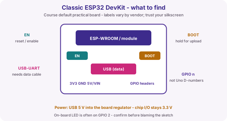
A typical 30- or 38-pin DevKit is more than the metal-can module. Trace these parts on your board before the first upload:
USB connector and USB-to-serial chip (needs a data cable). EN (reset/enable) and BOOT buttons. 3V3, GND and 5V/VIN pins. Two rows of GPIO headers labelled with GPIO numbers - not Uno D0-D13 numbers.
Many DevKits put the blue on-board LED on GPIO 2. If Blink does nothing, check the silkscreen before rewriting the sketch.
ESP32 versus Arduino Uno R3
Same IDE workflow idea (setup/loop), very different hardware. Treat voltage and pin maps carefully when you switch boards.
| Feature | Arduino Uno R3 | Typical ESP32-family board |
|---|---|---|
| Maker / MCU | Arduino / ATmega328P (8-bit AVR) | Espressif / ESP32-class SoC |
| CPU class | 16 MHz single core | Much faster; Xtensa or RISC-V (single- or dual-core) |
| Memory | 32 KB Flash, 2 KB SRAM | Megabytes of Flash, hundreds of KB SRAM (varies by module) |
| Logic voltage | 5 V I/O | 3.3 V I/O - do not feed 5 V into pins |
| Wi-Fi / Bluetooth | None on-board | Most chips: Wi-Fi and usually Bluetooth; ESP32-P4 needs a companion radio for wireless |
| ADC | 6 x 10-bit (A0-A5) | Multiple ADC channels; check the module pinout |
| USB / programming | USB-B serial bridge | USB-UART or native USB-C (board-dependent) |
| IDE support | Arduino AVR Boards | esp32 by Espressif Systems (Board Manager) |
| Shields / 5 V modules | Uno ecosystem | Often need level shifting or 3.3 V-safe modules |
Classic ESP32 (DevKit / WROOM class)
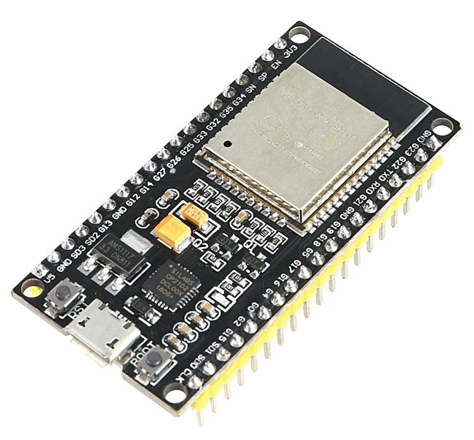
The original ESP32 (often sold as ESP32-DevKitC or ESP32-WROOM modules) uses Xtensa dual-core CPUs with 2.4 GHz Wi-Fi and Bluetooth Classic/BLE. It is the most common "ESP32" learners mean, and the default for later course sketches. The example photo is a common 38-pin DevKit V1 style board (ESP-WROOM-32, Micro-USB).
ESP32-C3
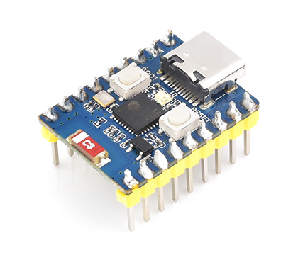
ESP32-C3 is a cost-focused RISC-V single-core chip with 2.4 GHz Wi-Fi 4 and Bluetooth LE. It is a strong budget step into Wi-Fi when you do not need the dual-core classic ESP32 or Thread/Zigbee radios. The example photo is a Waveshare ESP32-C3-Zero - a compact USB-C board; always match the IDE board entry and GPIO labels to your module.
ESP32-C5
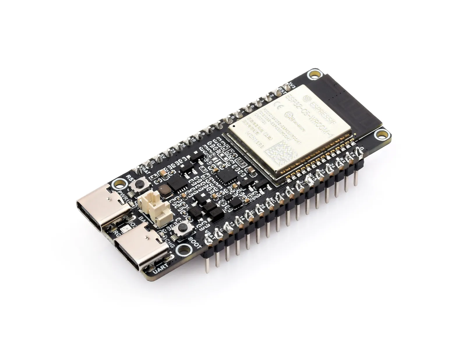
ESP32-C5 adds dual-band Wi-Fi 6 (2.4 GHz and 5 GHz) plus Bluetooth LE and IEEE 802.15.4 (useful for Matter / Thread-style IoT). Choose C5 when 5 GHz Wi-Fi or dual-band connectivity matters. The example photo is a Waveshare ESP32-C5-WIFI6-KIT (N16R4 class module).
ESP32-C6
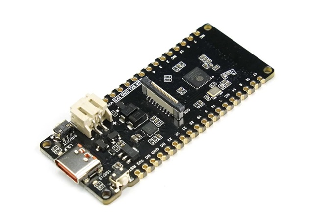
ESP32-C6 is a RISC-V IoT SoC with 2.4 GHz Wi-Fi 6, Bluetooth LE, and IEEE 802.15.4 for Zigbee / Thread / Matter-oriented designs. It is a common choice for modern smart-home nodes that need Wi-Fi 6 and 802.15.4 without 5 GHz. The example photo is a DFRobot FireBeetle 2 ESP32-C6.
ESP32-P4
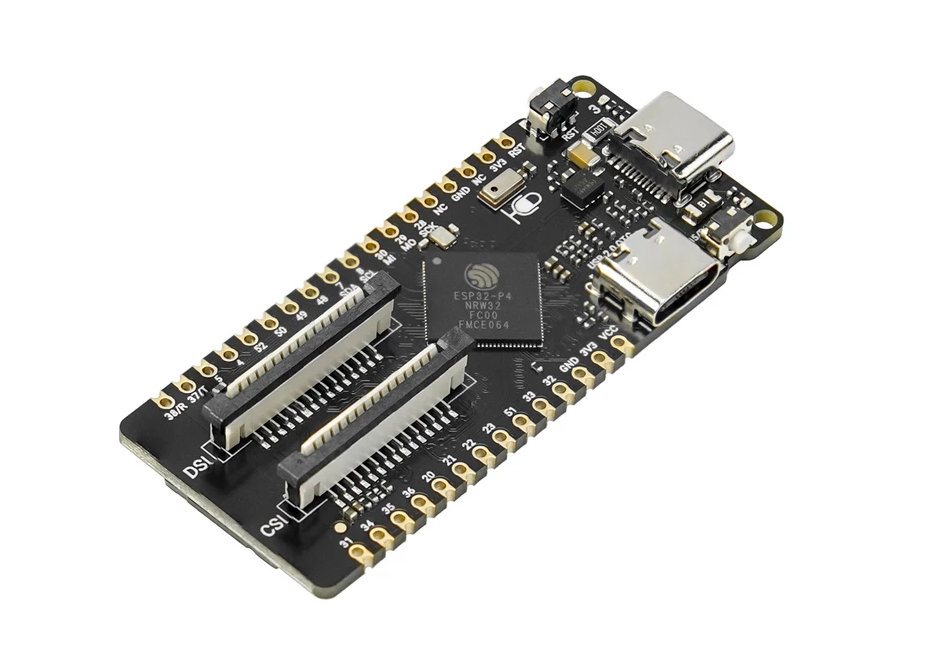
ESP32-P4 is Espressif's high-performance RISC-V SoC for rich human-machine interfaces and edge compute: dual-core CPU, MIPI-CSI camera and MIPI-DSI display paths, USB 2.0 HS, and media helpers such as H.264 encode. The P4 itself has no on-chip Wi-Fi or Bluetooth - many boards add a companion radio (often an ESP32-C6). The example photo is a DFRobot FireBeetle 2 ESP32-P4 with onboard MIPI CSI/DSI and a C6 co-processor for Wi-Fi 6. Choose P4 for displays, cameras and heavier local processing; choose a C-series or classic ESP32 when you only need a simple Wi-Fi node.
ESP32 versions at a glance
High-level comparison for course selection. Exact Flash/SRAM and pin counts depend on the module and vendor board.
| SoC | CPU | Wi-Fi | Bluetooth | 802.15.4 / Matter-oriented | Typical use |
|---|---|---|---|---|---|
| ESP32 (classic) | Xtensa dual-core | Wi-Fi 4 (2.4 GHz) | BT Classic + BLE | No | Course default for Wi-Fi labs; largest community examples |
| ESP32-C3 | RISC-V single-core | Wi-Fi 4 (2.4 GHz) | BLE | No | Budget Wi-Fi + BLE nodes |
| ESP32-C5 | RISC-V | Wi-Fi 6 dual-band (2.4 + 5 GHz) | BLE | Yes (IEEE 802.15.4) | Dual-band / 5 GHz Wi-Fi IoT |
| ESP32-C6 | RISC-V single-core | Wi-Fi 6 (2.4 GHz) | BLE | Yes (Zigbee/Thread/Matter path) | Smart-home / Matter-class nodes |
| ESP32-P4 | RISC-V dual-core (high perf.) | No on-chip (companion radio) | No on-chip (companion radio) | Via companion if fitted | HMI, MIPI camera/display, edge compute |
Add ESP32 support in Arduino IDE 2
Install Espressif's official board package once. Verify compiles on the PC; Upload sends the binary through the selected port. Wrong Board entry is a common cause of confusing upload failures.
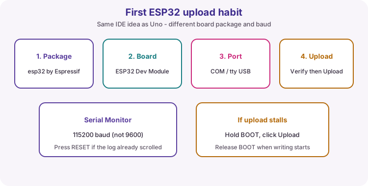
| Step | Action |
|---|---|
| 1 | File -> Preferences (Windows/Linux) or Arduino IDE -> Settings (macOS) |
| 2 | Additional Board Manager URLs: https://espressif.github.io/arduino-esp32/package_esp32_index.json |
| 3 | Boards Manager: search esp32; install esp32 by Espressif Systems |
| 4 | Tools -> Board -> esp32 -> ESP32 Dev Module (or your matching C3/C5/C6/P4 entry) |
| 5 | Tools -> Port -> the COM/tty device that appears when the board is plugged in |
| 6 | Verify, then Upload this lesson sketch; open Serial Monitor at 115200 |
Upload faults and the BOOT button
If Upload cannot connect: use a USB data cable, try another USB socket, and confirm the port appears only when the board is plugged in.
On many classic DevKits, hold BOOT, start Upload, then release BOOT when the tool begins writing. EN resets the board - useful after a stuck upload or to replay Serial startup messages.
| Symptom | Likely fix |
|---|---|
| No port listed | Data cable; drivers; another USB socket |
| Wrong board | ESP32 Dev Module for classic DevKit - not Uno |
| Upload timed out | Hold BOOT during connect; release when writing |
| Blank Serial | Baud 115200; press EN/RESET after open |
| LED never blinks | Confirm LED_BUILTIN / GPIO 2 on your silkscreen |
3.3 V safety when leaving the Uno
ESP32-family GPIO is 3.3 V. Never connect a 5 V Uno output directly into an ESP32 input. Many "5 V" sensors need level shifting or a 3.3 V-safe variant. USB often feeds 5 V into the DevKit regulator while chip I/O stays 3.3 V - lesson 36 goes deeper on rails and dividers.
Wiring and safe build sequence
- Connect the ESP32 with a USB data cable (not charge-only)
- Install esp32 by Espressif Systems using the Board Manager steps in this lesson
- Tools -> Board -> ESP32 Dev Module (classic DevKit) and select the correct port
- Locate EN, BOOT, 3V3, GND and the on-board LED (often GPIO 2) on your silkscreen
- Upload this sketch; open Serial Monitor at 115200
- If using an external LED: series resistor, safe GPIO, common GND; keep logic 3.3 V-compatible
Worked sketch
Download .ino sketch#ifndef LED_BUILTIN
#define LED_BUILTIN 2
#endif
const int ledPin = LED_BUILTIN;
void setup() {
pinMode(ledPin, OUTPUT);
Serial.begin(115200);
delay(500);
Serial.println("ESP32 ready - Serial at 115200");
}
void loop() {
digitalWrite(ledPin, HIGH);
Serial.println("LED on");
delay(500);
digitalWrite(ledPin, LOW);
Serial.println("LED off");
delay(500);
}How the code works
- Match Serial Monitor to 115200 - Uno examples often used 9600.
- LED_BUILTIN is often GPIO 2 on classic DevKits; change ledPin if your board differs.
- Upload uses the Espressif toolchain from Board Manager, not the Uno AVR core.
- A short delay after Serial.begin gives the USB-serial bridge time before the first print.
Test and record evidence
Practical evidence checklist
Common faults and checks
- Board package missing: confirm the Additional Board Manager URL and install esp32 by Espressif Systems.
- Wrong board selected: classic DevKit needs ESP32 Dev Module; C3/C5/C6/P4 need their own entries.
- No port: data cable, drivers, or another USB socket.
- Upload fails at connect: hold BOOT while uploading on some boards, then release.
- Blank Serial: set 115200 and press EN/RESET.
- LED silent: set ledPin to the GPIO labelled for the on-board LED.
- P4 board has no Wi-Fi in sketches: expected unless a companion radio is fitted and configured.
Check your understanding
Q1. What is the course default Board menu entry for classic DevKit labs?
Show answer
ESP32 Dev Module.
Q2. What Serial baud do ESP32 course sketches use?
Show answer
115200.
Q3. Name two parts to find on a classic DevKit besides the metal module.
Show answer
Examples: EN, BOOT, USB, 3V3, GND, 5V/VIN, GPIO headers.
Q4. What is the usual I/O voltage class for ESP32 pins compared with Uno R3?
Show answer
ESP32 is 3.3 V; Uno R3 is 5 V.
Q5. What Board Manager package author should you install for ESP32?
Show answer
Espressif Systems (package name esp32).
Q6. What should you try if Upload cannot connect on a classic DevKit?
Show answer
Hold BOOT during connect, then release when writing starts; also check data cable and port.
Q7. Why might a 5 V sensor output be unsafe on ESP32?
Show answer
It can over-voltage a 3.3 V GPIO without level shifting.
Q8. What is ESP32-P4 mainly for, and what does it lack on-chip?
Show answer
HMI / camera-display / edge compute; no on-chip Wi-Fi or Bluetooth.