
49. Over-the-Air Updates
Ship a field-updatable node: first USB flash enables OTA, then change the firmware version banner and blink over Wi-Fi.
Learning outcomes
- Explain why sealed devices need OTA
- Contrast ArduinoOTA with HTTP image pull
- Keep ArduinoOTA.handle() responsive with millis timing
- USB-flash once, then OTA-upload a visible behaviour change
- Apply hostname and password safety habits
Parts and preparation
ESP32 DevKit on the same LAN as your PC, USB for first flash, LED on GPIO 2, WiFi credentials.
Before power: inspect wiring, confirm supply voltage and ensure all connected circuits share GND.
Libraries for this lesson
In Arduino IDE 2 open Tools → Manage Libraries…. Search by the Library Manager name and install the package by the exact author below. Similar names from other authors can use different APIs and will break the example.
| Include | Library Manager name | Author | Install note |
|---|---|---|---|
WiFi.h | WiFi | Espressif | Built into the esp32 Arduino core. |
ArduinoOTA.h | ArduinoOTA | Espressif / Arduino | Built into the esp32 Arduino core. |
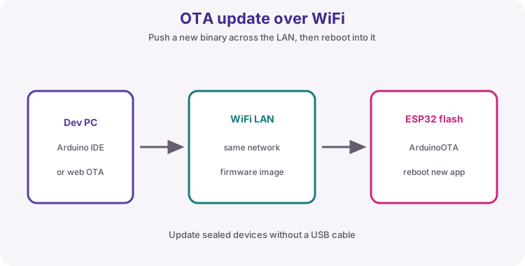
Project: Field-updatable node
Imagine the board is already installed in a ceiling box. You need to change behaviour without climbing a ladder for USB.
Sketch 1 (VERSION 1.0) enables OTA with a slow blink and a Serial banner. Sketch 2 (VERSION 1.1) is the update you push over the network port: faster blink and new banner. USB-upload sketch 1 first; OTA-upload sketch 2 to prove the field path.
ArduinoOTA versus HTTP OTA
ArduinoOTA: IDE pushes over the LAN - perfect for labs. HTTP OTA: device pulls an image URL - typical for fleets. This lesson is ArduinoOTA end to end.
| Style | Who starts | Use |
|---|---|---|
| ArduinoOTA | Developer PC | Lab / local |
| HTTP OTA | Device pull | Field fleets |
BasicOTA flow and handle()
Flash with OTA code over USB -> board joins WiFi -> Tools Port shows network hostname -> upload again. loop must call ArduinoOTA.handle() often. Use millis for blinking - never long delay() that starves handle().
Safety notes
Unique hostname per board on busy lab WiFi. setPassword outside trusted LANs. Keep a USB cable for recovery if an update fails mid-way.
Wiring and safe build sequence
- First flash: USB data cable
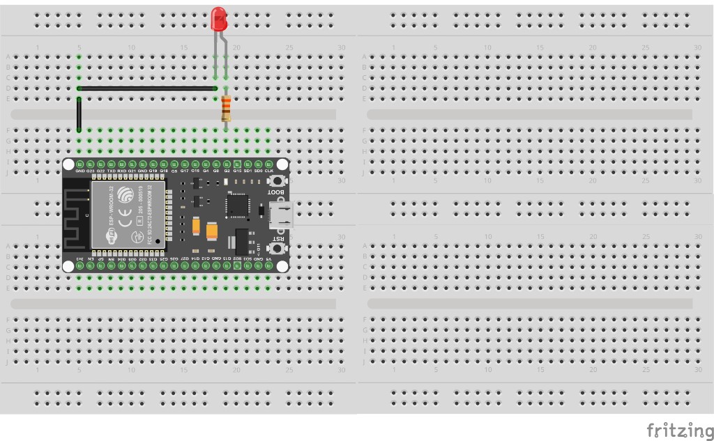
- GPIO 2 LED shows version behaviour
- PC and ESP32 on same WiFi
Worked sketch 1: Field node VERSION 1.0 (USB first)
Download .ino sketchWhat this sketch is for: Install the OTA service once over USB. Slow blink and banner VERSION 1.0 prove this build is running. handle() stays responsive because blinking uses millis.
#include <WiFi.h>
#include <ArduinoOTA.h>

const char* ssid = "YOUR_WIFI_SSID";
const char* password = "YOUR_WIFI_PASSWORD";
const char* version = "1.0";
const int ledPin = 2;
const unsigned long blinkMs = 800;
unsigned long lastToggle = 0;
bool ledOn = false;

void setup() {
  Serial.begin(115200);
  pinMode(ledPin, OUTPUT);

  WiFi.mode(WIFI_STA);
  WiFi.begin(ssid, password);
  while (WiFi.status() != WL_CONNECTED) {
    delay(500);
    Serial.print(".");
  }
  Serial.println();
  Serial.print("IP ");
  Serial.println(WiFi.localIP());

  ArduinoOTA.setHostname("wilteq-esp32");
  // ArduinoOTA.setPassword("lab-password");

  ArduinoOTA.onStart([]() { Serial.println("OTA start"); });
  ArduinoOTA.onEnd([]() { Serial.println("\nOTA end"); });
  ArduinoOTA.onError([](ota_error_t error) {
    Serial.printf("OTA error %u\n", error);
  });
  ArduinoOTA.begin();

  Serial.print("Field node VERSION ");
  Serial.println(version);
  Serial.println("OTA ready - network port wilteq-esp32");
}

void loop() {
  ArduinoOTA.handle();

  if (millis() - lastToggle >= blinkMs) {
    lastToggle = millis();
    ledOn = !ledOn;
    digitalWrite(ledPin, ledOn ? HIGH : LOW);
  }
}
How the code works
- millis blink never blocks ArduinoOTA.handle().
- Hostname wilteq-esp32 must be unique on a shared lab SSID - change it if needed.
- Uncomment setPassword outside a closed classroom LAN.
Worked sketch 2: Field node VERSION 1.1 (OTA this one)
Download .ino sketchWhat this sketch is for: After sketch 1 is running, select the network port and upload THIS sketch over OTA. Success: Serial shows VERSION 1.1 and the LED blinks faster - no USB required for the update. Match the breadboard layout below before upload.
#include <WiFi.h>
#include <ArduinoOTA.h>

const char* ssid = "YOUR_WIFI_SSID";
const char* password = "YOUR_WIFI_PASSWORD";
const char* version = "1.1";
const int ledPin = 2;
const unsigned long blinkMs = 150;
unsigned long lastToggle = 0;
bool ledOn = false;

void setup() {
  Serial.begin(115200);
  pinMode(ledPin, OUTPUT);

  WiFi.mode(WIFI_STA);
  WiFi.begin(ssid, password);
  while (WiFi.status() != WL_CONNECTED) {
    delay(500);
    Serial.print(".");
  }
  Serial.println();
  Serial.println(WiFi.localIP());

  ArduinoOTA.setHostname("wilteq-esp32");
  // ArduinoOTA.setPassword("lab-password");
  ArduinoOTA.onStart([]() { Serial.println("OTA start"); });
  ArduinoOTA.onEnd([]() { Serial.println("\nOTA end"); });
  ArduinoOTA.begin();

  Serial.print("Field node VERSION ");
  Serial.println(version);
  Serial.println("OTA ready");
}

void loop() {
  ArduinoOTA.handle();
  if (millis() - lastToggle >= blinkMs) {
    lastToggle = millis();
    ledOn = !ledOn;
    digitalWrite(ledPin, ledOn ? HIGH : LOW);
  }
}
How the code works
- Only version string and blinkMs changed - enough to prove the new image.
- If OTA fails, recover with USB and sketch 1.
- Same hostname and WiFi credentials as sketch 1.
- Build from the breadboard photo: indicator LED on GPIO 2.
Test and record evidence
Practical evidence checklist
Common faults and checks
- No network port: same LAN, firewall/mDNS, unique hostname, reboot IDE.
- OTA stalls: confirm handle() runs; avoid delay-based blink.
- Failed mid-update: USB recover with sketch 1.
Check your understanding
Q1. What field problem does OTA solve?
Show answer
Updating firmware without physical USB access.
Q2. Which call must run often?
Show answer
ArduinoOTA.handle().
Q3. Why avoid delay() for the blink here?
Show answer
Long delays starve handle() and can miss OTA.
Q4. How do you prove sketch 2 arrived?
Show answer
VERSION 1.1 banner and faster blink after network upload.
Q5. ArduinoOTA vs HTTP OTA?
Show answer
IDE push on LAN vs device pulls an image URL.
Q6. Why a unique hostname?
Show answer
Avoid flashing someone else's board on a shared WiFi.
Q7. Why keep USB around while learning?
Show answer
Recovery if an OTA image fails.
Q8. First enable step?
Show answer
USB-upload a sketch that connects WiFi and begins ArduinoOTA.