
50. Capstone: Networked Room Node
Build an assessment-ready room node: STA WiFi, live comfort reading on the web, JSON for programs, and a threshold alert LED.
Learning outcomes
- Integrate STA WiFi, ADC sensing and WebServer into one reliable room node
- Serve a live HTML dashboard and a /json reading
- Drive an alert LED from a calibrated threshold
- Follow sense -> decide -> connect -> serve integrate order
- Demonstrate and explain the system at pass level without MQTT/NeoPixel/OTA
Parts and preparation
ESP32 DevKit, USB data cable, 10 k ohm potentiometer on GPIO 34 (room comfort / level stand-in), LED + series resistor on GPIO 2 (alert lamp), breadboard and jumpers. Libraries: WiFi + WebServer only (esp32 core).
Before power: inspect wiring, confirm supply voltage and ensure all connected circuits share GND.
Libraries for this lesson
In Arduino IDE 2 open Tools → Manage Libraries…. Search by the Library Manager name and install the package by the exact author below. Similar names from other authors can use different APIs and will break the example.
| Include | Library Manager name | Author | Install note |
|---|---|---|---|
WiFi.h | WiFi | Espressif | Built into the esp32 Arduino core. |
WebServer.h | WebServer | Espressif | Built into the esp32 Arduino core. |
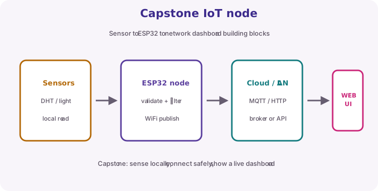
Project: Networked room node
Build a small room monitor you could leave on a bench: anyone on the same WiFi opens a page, sees a live comfort level (potentiometer standing in for light, CO2 proxy, or knob setpoint), and an alert LED lights when the level crosses your threshold.
Pass requires a reliable demo and a clear explanation - not every Unit I feature at once. MQTT, NeoPixel status tiles, deep sleep and OTA are stretch only after the node is solid.
Integrate in order
1) Power and 3.3 V pot (never 5 V into ADC). 2) Sense: Serial-print analogRead on GPIO 34. 3) Decide: threshold drives alert LED. 4) Connect: STA, print IP. 5) Serve: / for humans, /json for programs. 6) Loop: sample + handleClient, no long delay.
If something fails, isolate the last block that worked.
| Block | Pass evidence |
|---|---|
| Sense | Page/Serial value moves with the pot |
| Decide | Alert LED flips near your threshold |
| Connect | LAN IP printed; phone on same SSID |
| Serve | Dashboard updates; /json matches |
GPIO 34 and ADC with WiFi
GPIO 34 is ADC1 input-only on classic DevKits - correct while WiFi runs. analogRead is 0-4095 at 12-bit. Calibrate threshold by watching live values. The pot is a stand-in: say in your demo what real sensor you would swap in later.
| Signal | Wiring |
|---|---|
| Pot ends | 3V3 and GND |
| Pot wiper | GPIO 34 |
| Alert LED | GPIO 2 via resistor |
HTML dashboard and JSON
Humans get / with room name and meta refresh. Programs get /json: {"room":"Lab room","level":2048,"threshold":2000,"alert":true}. String building is enough - ArduinoJson optional stretch.
Assessment rubric (pass level)
Reliable demo first. Extra features do not rescue a flaky node.
| Criterion | What good looks like |
|---|---|
| Bring-up | IP on Serial; correct board/port |
| Dashboard | Live level as pot turns |
| Alert | LED tracks threshold clearly |
| JSON | /json matches the page |
| Safety | 3V3 pot; series LED resistor |
| Explain | STA, handleClient, ADC1 in your words |
| Fault-find | Isolate wiring vs WiFi vs code |
Stretch only after a pass
Not required: MQTT publish (44), NeoPixel status colour (39-40), deep sleep pulses (47), OTA field updates (49), SoftAP setup (45). Pick at most one stretch.
Wiring and safe build sequence
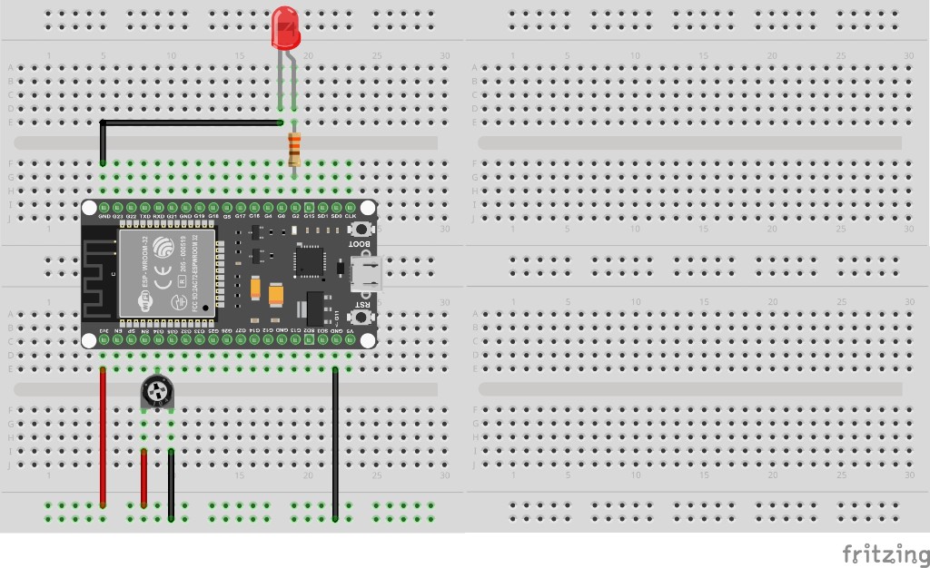
- Potentiometer: 3V3 -> one end, GND -> other end, wiper -> GPIO 34
- Alert LED: GPIO 2 -> 220-330 ohm -> LED anode; cathode -> GND
- USB for power; phone/PC on the same WiFi as the ESP32
Worked sketch: Networked room node
Download .ino sketchWhat this sketch is for: Full pass demo in one sketch: join WiFi, show Lab room comfort level on / and /json, light the alert LED above threshold. Calibrate threshold to your pot before the assessment. Match the breadboard layout below before upload.
#include <WiFi.h>
#include <WebServer.h>

const char* ssid = "YOUR_WIFI_SSID";
const char* password = "YOUR_WIFI_PASSWORD";
const char* roomName = "Lab room";

const int potPin = 34;
const int alertPin = 2;
const int threshold = 2000;

WebServer server(80);
int level = 0;
bool alertOn = false;

String getHTML() {
  String html = R"=====(
<!DOCTYPE html>
<html>
<head>
  <meta http-equiv="refresh" content="2">
  <meta name="viewport" content="width=device-width, initial-scale=1">
  <title>Room node</title>
  <style>
    body { font-family: sans-serif; text-align: center; margin-top: 40px; }
  </style>
</head>
<body>
  <h1>)=====";
  html += roomName;
  html += R"=====(</h1>
  <p>Comfort level: )=====";
  html += String(level);
  html += R"=====(</p>
  <p>Alert threshold: )=====";
  html += String(threshold);
  html += R"=====(</p>
  <p>Alert lamp: )=====";
  html += alertOn ? "ON" : "OFF";
  html += R"=====(</p>
  <p><a href="/json">/json</a></p>
</body>
</html>
)=====";
  return html;
}

void handleRoot() {
  server.send(200, "text/html", getHTML());
}

void handleJson() {
  String body = "{"room":"";
  body += roomName;
  body += "","level":";
  body += String(level);
  body += ","threshold":";
  body += String(threshold);
  body += ","alert":";
  body += alertOn ? "true" : "false";
  body += "}";
  server.send(200, "application/json", body);
}

void setup() {
  Serial.begin(115200);
  pinMode(alertPin, OUTPUT);

  WiFi.mode(WIFI_STA);
  WiFi.begin(ssid, password);
  while (WiFi.status() != WL_CONNECTED) {
    delay(500);
    Serial.print(".");
  }
  Serial.println();
  Serial.print("Room node - open http://");
  Serial.println(WiFi.localIP());

  server.on("/", handleRoot);
  server.on("/json", handleJson);
  server.begin();
}

void loop() {
  level = analogRead(potPin);
  alertOn = level > threshold;
  digitalWrite(alertPin, alertOn ? HIGH : LOW);
  server.handleClient();
}
How the code works
- roomName appears on the dashboard - change it for your assessment label.
- threshold 2000 is a starting point on 12-bit ADC - calibrate live.
- meta refresh updates humans; /json serves programs.
- No long delay() - handleClient stays responsive.
- Build from the breadboard photo: pot on GPIO 34, alert LED on GPIO 2.
Test and record evidence
Practical evidence checklist
Common faults and checks
- ADC stuck: 3V3 pot, wiper on GPIO 34, common GND.
- Page static: same SSID as phone; exact IP from Serial.
- Alert always on/off: recalibrate threshold.
- WiFi fail: 2.4 GHz credentials as in Unit H.
Check your understanding
Q1. What are you building?
Show answer
A networked room node with live web level and threshold alert.
Q2. Which WiFi mode?
Show answer
Station (STA) on the lab router.
Q3. Why GPIO 34?
Show answer
ADC1 input-only pin suitable with WiFi on classic ESP32.
Q4. Why not 5 V on the pot?
Show answer
ESP32 ADC is 3.3 V class.
Q5. What does /json provide?
Show answer
Machine-readable room, level, threshold, alert.
Q6. Why call handleClient every loop?
Show answer
Serve browsers while still sampling.
Q7. Is MQTT required to pass?
Show answer
No - stretch only.
Q8. What should a pass demo prove?
Show answer
Live dashboard, matching JSON, alert LED, and a clear STA/ADC explanation.
Q9. Integrate order first step after power?
Show answer
Sense on Serial before adding WiFi and the web UI.