
38. GPIO, PWM, ADC and UART on ESP32
Map Uno I/O habits onto ESP32 and build a bench lamp dimmer with a clear brightness percent readout.
Learning outcomes
- Map Uno digitalWrite / analogWrite / Serial onto ESP32 GPIO habits
- Dim an LED with analogWrite (LEDC) from a 12-bit pot
- Build a bench lamp dimmer that reports brightness percent
- Avoid using input-only pins as outputs
- Use Serial at 115200 for ESP32 debugging
Parts and preparation
ESP32 DevKit, LED, 220-330 ohm series resistor, 10 k ohm potentiometer, breadboard, jumper wires.
Before power: inspect wiring, confirm supply voltage and ensure all connected circuits share GND.
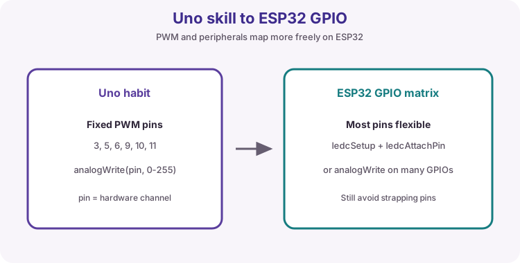
Project: Bench lamp dimmer
Build a small bench lamp control: pot sets brightness, Serial shows percent so you can match a desired level. Same skills later drive room lights over Wi-Fi (lesson 42) - start local and tactile.
Sketch 1 links pot to PWM duty. Sketch 2 is the product readout: Lab lamp brightness percent with millis-timed Serial.
Skills you already have
digitalWrite, analogWrite, analogRead and Serial still work. Write silkscreen GPIO numbers (2, 34), not Uno D-labels. Serial at 115200.
| Uno habit | ESP32 course note |
|---|---|
| digitalWrite(D8, HIGH) | digitalWrite(gpio, HIGH) with labelled GPIO |
| analogWrite on ~ pins | analogWrite via LEDC on many safe GPIOs |
| analogRead 0-1023 | 0-4095 after analogReadResolution(12) |
| Serial 9600 common | Serial 115200 for ESP32 course sketches |
Pick pins that can do the job
GPIO 34-39 are input-only on classic ESP32 - pot yes, LED no. Course wiring: pot on 34, lamp LED / on-board LED on GPIO 2. Pot from 3V3.
| Pin | This lesson |
|---|---|
| GPIO 34 | Pot wiper - input-only ADC |
| GPIO 2 | Lamp LED / PWM |
| 3V3 / GND | Pot outer legs |
PWM via LEDC / analogWrite
analogWrite(pin, duty) uses LEDC under the hood. map() converts 0-4095 pot codes into 0-255 duty.
int raw = analogRead(34);
int duty = map(raw, 0, 4095, 0, 255);
analogWrite(2, duty);
UART reminder
USB Serial is still Serial. Print brightness while you turn the pot so ADC and eye agree.
Wiring and safe build sequence
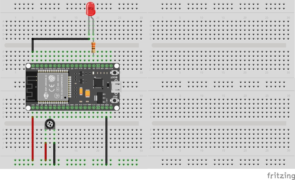
- Pot outer legs -> 3V3 and GND; wiper -> GPIO 34
- GPIO 2 -> 220-330 ohm -> LED anode; cathode -> GND (or on-board LED)
- Serial Monitor 115200
Worked sketch 1: Pot to PWM duty
Download .ino sketchWhat this sketch is for: Discovery: turn the pot and watch LED brightness track a 0-255 duty printed on Serial.
const int potPin = 34;
const int ledPin = 2;

void setup() {
  pinMode(ledPin, OUTPUT);
  Serial.begin(115200);
  analogReadResolution(12);
}

void loop() {
  int raw = analogRead(potPin);
  int duty = map(raw, 0, 4095, 0, 255);
  analogWrite(ledPin, duty);
  Serial.println(duty);
  delay(100);
}
How the code works
- map scales 12-bit ADC into Uno-like 0-255 duty.
- GPIO 34 cannot drive the LED - it is input-only.
Worked sketch 2: Bench lamp percent readout
Download .ino sketchWhat this sketch is for: Useful dimmer UI: same hardware, but Serial shows Lab lamp brightness as a percent updated every 200 ms with millis (no long delay). Match the breadboard layout below before upload.
const int potPin = 34;
const int lampPin = 2;
unsigned long lastPrint = 0;

void setup() {
  pinMode(lampPin, OUTPUT);
  Serial.begin(115200);
  analogReadResolution(12);
  Serial.println("Bench lamp dimmer");
}

void loop() {
  int raw = analogRead(potPin);
  int duty = map(raw, 0, 4095, 0, 255);
  analogWrite(lampPin, duty);

  if (millis() - lastPrint >= 200) {
    lastPrint = millis();
    int pct = map(duty, 0, 255, 0, 100);
    Serial.print("Lab lamp ");
    Serial.print(pct);
    Serial.println("%");
  }
}
How the code works
- PWM updates every loop; Serial prints on a millis timer.
- Percent is easier to talk about in a demo than raw duty.
- Later Wi-Fi remotes can show the same percent on a web page.
- Build from the breadboard photo: pot on GPIO 34, lamp LED on GPIO 2.
Test and record evidence
Practical evidence checklist
Common faults and checks
- No dimming: GPIO 2 wiring / on-board LED mapping.
- Stuck bright: pot on 34 with 3V3/GND.
- Values near 1023 only: analogReadResolution(12).
- External LED: never omit the series resistor.
Check your understanding
Q1. What project is this?
Show answer
A bench lamp dimmer with brightness percent readout.
Q2. What sits behind analogWrite PWM?
Show answer
LEDC.
Q3. map range for pot to duty?
Show answer
map(raw, 0, 4095, 0, 255).
Q4. Can GPIO 34 drive the lamp LED?
Show answer
No - input-only on classic ESP32.
Q5. Serial baud?
Show answer
115200.
Q6. Why power the pot from 3V3?
Show answer
Keep wiper voltage ESP32-safe.
Q7. Why print percent in sketch 2?
Show answer
Human-readable setpoint for demos and later UIs.