
37. Pinout, Strapping Pins, ADC, DAC and Touch
Learn strapping pins and 12-bit ADC, then build a trim setpoint reader that reports LOW/MID/HIGH bands.
Learning outcomes
- Explain the GPIO matrix idea at course level
- List classic strapping pins and why they matter at boot
- Use 12-bit analogRead (0-4095) on GPIO 34
- Build a trim setpoint reader with voltage estimate and bands
- State DAC and touch as awareness topics on classic ESP32
Parts and preparation
ESP32 DevKit, 10 k ohm potentiometer, breadboard, jumper wires.
Before power: inspect wiring, confirm supply voltage and ensure all connected circuits share GND.
Project: Trim setpoint reader
Many products hide a trim pot for threshold, brightness or calibration. You will read a pot on GPIO 34 and turn it into a human setpoint display.
Sketch 1 proves 12-bit ADC codes. Sketch 2 is the useful reader: print raw, estimated volts, and LOW/MID/HIGH band for your trim.
GPIO matrix idea
Many peripheral signals can route to a wide set of GPIOs - with exceptions. Trust silkscreen and Espressif notes over Uno D-numbers. Some pins are input-only; some are strapping; some serve flash on modules.
Strapping pins
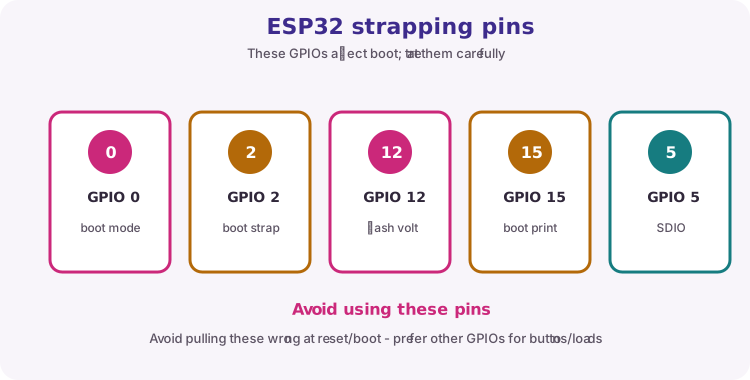
At reset, classic ESP32 samples GPIO 0, 2, 12, 15 (and often 5). GPIO 0 LOW at reset often enters download mode - useful for flashing, confusing with a casual button.
| Pin (classic) | Course caution |
|---|---|
| GPIO 0 | Boot / download strap |
| GPIO 2 | Strapping; often on-board LED |
| GPIO 12 | Flash voltage select risk |
| GPIO 15 | Avoid unwanted pull at boot |
| GPIO 5 | Strapping on classic - check docs |
ADC: 12-bit, attenuation and nonlinearity
12-bit codes 0-4095 with analogReadResolution(12). Finer than Uno 0-1023, but nonlinear at the ends. Power the pot from 3V3. GPIO 34 is input-only - ideal for the wiper. Treat readings as useful, not metrology-grade.
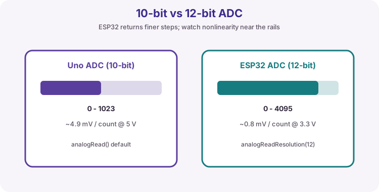
| Item | Uno R3 default | ESP32 course default |
|---|---|---|
| Resolution | 10-bit (0-1023) | 12-bit (0-4095) |
| Course pot pin | A0 | GPIO 34 (input-only) |
DAC and touch (awareness)
Classic ESP32 DAC on GPIO 25/26; many RISC-V parts differ. touchRead exists on supported pins. This lesson's practical path is the trim pot on GPIO 34.
Wiring and safe build sequence
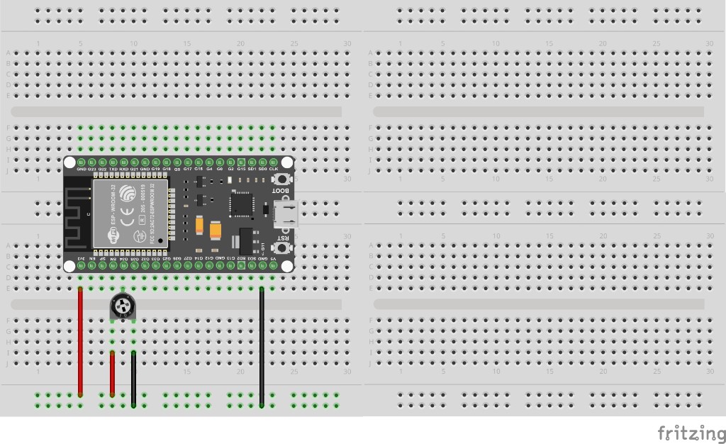
- Potentiometer outer legs -> 3V3 and GND; wiper -> GPIO 34
- USB to DevKit; Serial Monitor 115200
Worked sketch 1: Prove 12-bit ADC
Download .ino sketchWhat this sketch is for: Discovery: turn the pot and watch raw codes move through roughly 0-4095.
const int potPin = 34;

void setup() {
  Serial.begin(115200);
  analogReadResolution(12);
}

void loop() {
  int raw = analogRead(potPin);
  Serial.println(raw);
  delay(200);
}
How the code works
- analogReadResolution(12) selects 0-4095 codes.
- GPIO 34 is input-only - do not digitalWrite it.
- Power the pot from 3V3, not 5 V.
Worked sketch 2: Trim setpoint reader
Download .ino sketchWhat this sketch is for: Useful calibration tool: print raw ADC, estimated volts, and LOW/MID/HIGH band so you can set thresholds for later lamps and alerts. Match the breadboard layout below before upload.
const int potPin = 34;
unsigned long lastPrint = 0;

const char* band(int raw) {
  if (raw < 1200) return "LOW";
  if (raw < 2800) return "MID";
  return "HIGH";
}

void setup() {
  Serial.begin(115200);
  analogReadResolution(12);
  Serial.println("Trim setpoint reader");
}

void loop() {
  if (millis() - lastPrint < 250) return;
  lastPrint = millis();

  int raw = analogRead(potPin);
  float volts = raw * (3.3f / 4095.0f);
  Serial.print("raw ");
  Serial.print(raw);
  Serial.print("  ");
  Serial.print(volts, 2);
  Serial.print(" V  ");
  Serial.println(band(raw));
}
How the code works
- Band thresholds are teaching defaults - retune for your pot travel.
- Voltage estimate assumes ~0-3.3 V full scale - ESP32 ADC is approximate.
- Use these bands later as alert thresholds in the Unit I capstone.
- Build from the breadboard photo: 3V3 and GND to pot ends; wiper to GPIO 34.
Test and record evidence
Practical evidence checklist
Common faults and checks
- Stuck mid: wiper on 34, outers on 3V3/GND.
- Only to 1023: call analogReadResolution(12).
- Noisy ends: expected somewhat - average if needed.
Check your understanding
Q1. What project is sketch 2?
Show answer
A trim setpoint reader with voltage and LOW/MID/HIGH bands.
Q2. 12-bit analogRead range?
Show answer
0 to 4095.
Q3. Name two classic strapping pins
Show answer
Any two of GPIO 0, 2, 12, 15 (and 5).
Q4. Why GPIO 34 for the pot?
Show answer
Input-only ADC pin on classic ESP32.
Q5. Classic DAC pins?
Show answer
GPIO 25 and 26 on classic ESP32.
Q6. Power the pot from 5 V?
Show answer
No - use 3V3.
Q7. Why are band labels useful?
Show answer
They turn raw codes into setpoint language for later projects.